Strain gauges are resistance based passive electrical transducers that work on piezoresistive effect.
Principle:
Resistance of a strained wire is more than the resistance of a un-strained wire of same dimensions.
In other words, compression or expansion of a metal of given dimension alters the resistance of the metal. Mathematically,
 A change in length (l) or Cross sectional area (A) of the wire alters the resistance (R).
Gauge Factor
Consider a metal wire with length L and cross sectional area D with a force F applied on either ends.
 The dimensions of the wire changes to L+∆L and D+∆D.

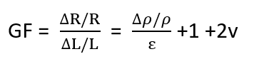
where v is poisson’s ratio and ρ is resistivity. (Approximation factors reduce the length and area to 1+2V.)
Piezoreistive effect
It is the change in resistivity of a material when mechanical strain is applied. While the effect of this in the material is negligible, the gauge factor becomes dependent only on geometric factors so it is; GF = 1+ 2V However, most commonly used strain gauges work on piezoresistivity , eg: Constantan is material where piezoresistivity is around 20% of the GF. For a video tutorial on derivation of gauge factor and its relation to poisson’s ratio click here
Gauge factor for different materials
| Material | Gauge Factor |
|---|---|
| Metal foil strain gauge | 2-5 |
| Thin-film metal (e.g. constantan) | 2 |
| Single crystal silicon | -125 to + 200 |
| Polysilicon | ±30 |
| Thick-film resistors | 100 |
| p-type Ge | 102 |
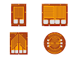
Types of Strain gauges
Strain gauges consist of very fine metallic wires that are arranged in a grid pattern attached to a flexible substrate called the carrier. The carrier is in close contact with the test subject so that any pressure on the subject translates to the movement of the carrier which in turn leads to compression or expansion of the metal wires. The foil is shaped as a grid to increase the area over which the forces act, giving a reliable output. These strain gauges are attached to arms of a Wheatstone bridge from which the voltage corresponding to the resistance change is measured. Depending on the design of the strain gauges they are classified into many types.
a. Unbounded Metal Strain gauge
The wire is not completely bonded with the carrier. It consists of a fixed body and a movable part. Metal wires connect these two parts and the movable part is in contact with the specimen.

Application of unbounded metal strain gauge:
- Used in applications where there is a need for removable gauges.
- Force, Pressure and Acceleration are some quantities measured
Advantages of unbonded metal strain gauge: High Accuracy Disadvantages of unbonded metal strain gauge: More space is occupied.
b. Bonded Metal wire Type
The metal wire is bonded to the carrier with epoxy. And the whole structure is attached to the specimen.

Advantages of bonded metal wire type strain gauge
- Inexpensive
- Small
- Temperature dependence is less
- Very sensitive
- For vibrational sensing and load sensing ( Static and dynamic Load)
Disadvantages of bonded metal wire type strain gauge Susceptible to creep error. Since they are highly sensitive and directly bonded to the specimen, over time due to wear of the adhesive will reduce its accuracy.
c. Bonded metal foil strain gauge
Similar to the metal wire strain gauge, only foil is used in place of thin metallic wires. They are manufactured by photo-etching process. They can take different shapes rather than the comb like structure of the metal foil
Advantages of Bonded metal foil strain gauge
- They have all the advantages of bonded metal wire strain gauge. In addition they reduce the transverse sensitive.
- They are much cheaper due to ease in manufacturing
d. Thin film strain gauge
This does not need adhesive. This is manufactured by deposition of a insulating layer followed by the deposition of the metal onto the specimen. Depending on the deposition technique, thin film strain gauges are of two types.
- Vacuum deposition
- Sputtering technique

Advantages of Thin film strain gauge Since there is molecular attachment, there is more stability and less susceptible to creep error.
e. Semiconductor Strain gauges.
Using deposition of semiconductors by semiconductor fabrication techniques of photo lithography and molecular beam epitaxy, they have high pezoresistive properties which means that the G.F is very high.
 Advantages of Semiconductor Strain gauges
- Most sensitive
- Very cheap
- Strong output signal (high GF)
- No creep (no bonding)
- High pressure range
Disadvantages of Semiconductor Strain gauges
- Temperature sensitive (Semiconductors are highly sensitive to small variation in temperatures)
- Non linear output.
Rosette strain gauge
These are strain gauges that are designed to be multidirectional. Since unidirectional strain gauges can only measure the strain in the direction of its alignment, it does not provide detailed data.

These strain gauges are connected in star or delta connections.
Temperature dependence of strain gauges
Resistance of the material changes due to temperature in addition to the strain and geometrical factors discussed above. In that case, the resistance change is given as

In order to minimize the error due to temperature and creep, compensations are provided for the strain gauges when it is connected to the Wheatstone bridge.