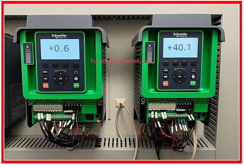
Wiring and Cable Selection for VFD Panels
1). Motor Output Wires
First, when it comes to motor output, utilize shielded VFD grade cables.
The electromagnetic interference (EMI) is decreased as a result.
Make sure that the shield is only grounded at the driving end.
2). Avoid Mixing Input, Output & Control Wire
In the same duct, you should never mix the wiring for the input, output, and control.
When it comes to noise, power and control lines should always be kept separate.
3). Use dv/Dt Filter
Use a dv/dt filter or an output reactor for motor wires that are longer than fifty meters.
It prevents voltage spikes from damaging the insulation and the bearings of the motor.
For the input cable, which is made of copper, the current divided by 2.5 equals the cable size in millimeters squared.
4). Copper Input Cable
If the input of the variable frequency drive (VFD) is 100A, then the output of the VFD is 100 ÷ 2.5 = 40 mm² copper. For aluminum, the output is 1.5 A per mm².
5). Copper Motor Cable
The current divided by 2.5 equals the cable size in millimeters squared
For instance, the motor FLC is equal to 75A, which results in 75 multiplied by 2.5, which is 30 mm3 of copper.
6). Use 1.0 or 1.5 mm² Control Wiring
It is recommended that the control wiring be either 1.0 mm2 or 1.5 mm2 (twisted pair for analog use).
Twisted pair is the method of choice for analog signals such as 4–20 mA or 0–10V.
You can also follow us on AutomationForum.co, Facebook and Linkedin to receive daily Instrumentation updates.
You can also follow us on ForumElectrical.com , Facebook and Linkedin to receive daily Electrical updates.
