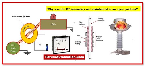
There is a fundamental difference between the operation of a Power Transformer (PT) and a Current Transformer (CT) in order to fully understand this concept.
The primary current in a power transformer is equal to the secondary current, as shown by the mmf balance equation N1I1 = N2I2.
The primary current in a Current Transformer (CT) is proportional to the current being carried by the load. Since the CT is wired in series with the supply.
Therefore, CT’s primary current remains unchanged whether the secondary is loaded or not.
During normal operation, the CT’s primary & secondary windings generate mutually opposing magnetic fields (mmf), as specified by Lenz’s law. Secondary mmf is smaller than primary mmf.
Therefore, there is a minimal amount of network mmf. This magnetizing mmf is essential to CT and is referred to as the net-working mmf.
When the secondary winding is disconnected, the secondary current is zero. Even though the primary current is unchanged.
Therefore, the principal current N1I1 is responsible for the network’s mmf. This high mmf will cause enormous fluxes in the center of CT, which will eventually lead to saturation.
Again, the massive core flux causes massive voltage to be generated across the secondary terminal of the CT via significant flux linkage in the secondary winding.
Insulation breakdown is imminent due to the high voltage across the secondary terminal.
Since CT has a potentially large secondary voltage, no one should ever operate with it while the primary voltage is active.
So, if the CT’s secondary circuit is left open, a large voltage may develop up on the device’s secondary terminal, putting workers and machinery at risk of electrical shock.
Apart from “Excitation Voltage,” the term “Burden Voltage” can be used to describe this condition.
