Why does a smart transmitter show stable PV locally but unstable values in the DCS?
Why does a smart transmitter show stable PV locally but unstable values in the DCS?
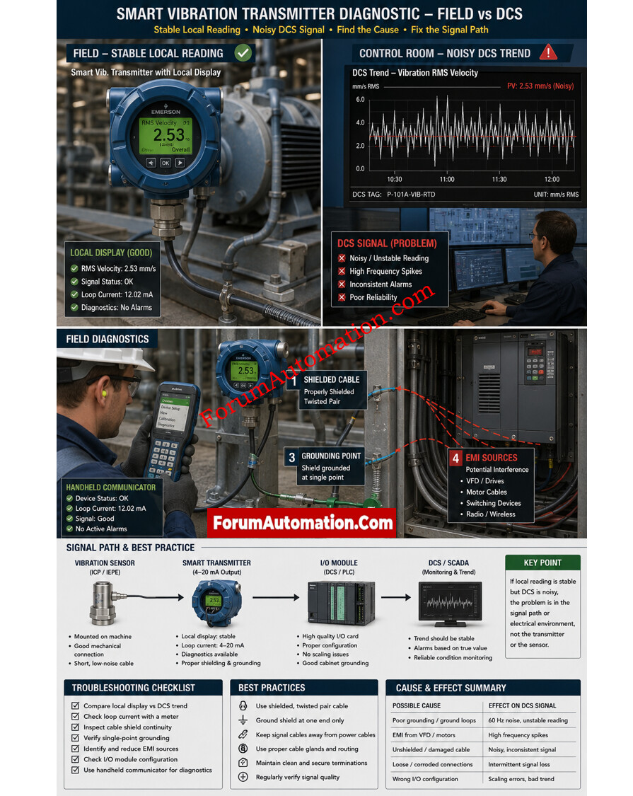
In some cases the two sites are not reading the same signal path . A smart transmitter can show a steady local PV while the DCS is showing an erratic value . The transmitter may be internally dampening or filtering the measurement, while the DCS input is receiving raw loop noise, scan jitter or scaling difficulties.
Begin with the comparison of three points; the local display, the transmitter output and the DCS input card. If local value is quiet but DCS trend is noisy, check wiring of the loop, shield termination and tightness of terminals. Check for EMI pickup from VFD cables, motor starters or relay cabinets. Also check DCS configuration, notably input range, engineering units, update rate, and any extra filters.
Sometimes the process itself is changing faster than the transmitter display can show. Internal damping can calm local PV, but the DCS can show every little motion. This gives an impression of instability. Communication problems can be important as well: a defective HART connection, bad power supply or an unstable analog card might lead to irregular values downstream.
The practice test is basic. Measure and trend the loop current, compare with transmitter diagnostics and verify the DCS signal at the same time. If the current is steady, the problem is probably in the DCS hardware or configuration. If the current is unsteady, check wiring, ground, noise sources. In most cases the error is not the sensor element but the signal channel between field and control system .