The typical setting range of an overvoltage relay (ANSI 59) in power systems depends on the application level and the system voltage but standard practice follows the well accepted protection guidelines.
Typical Overvoltage Relay Settings
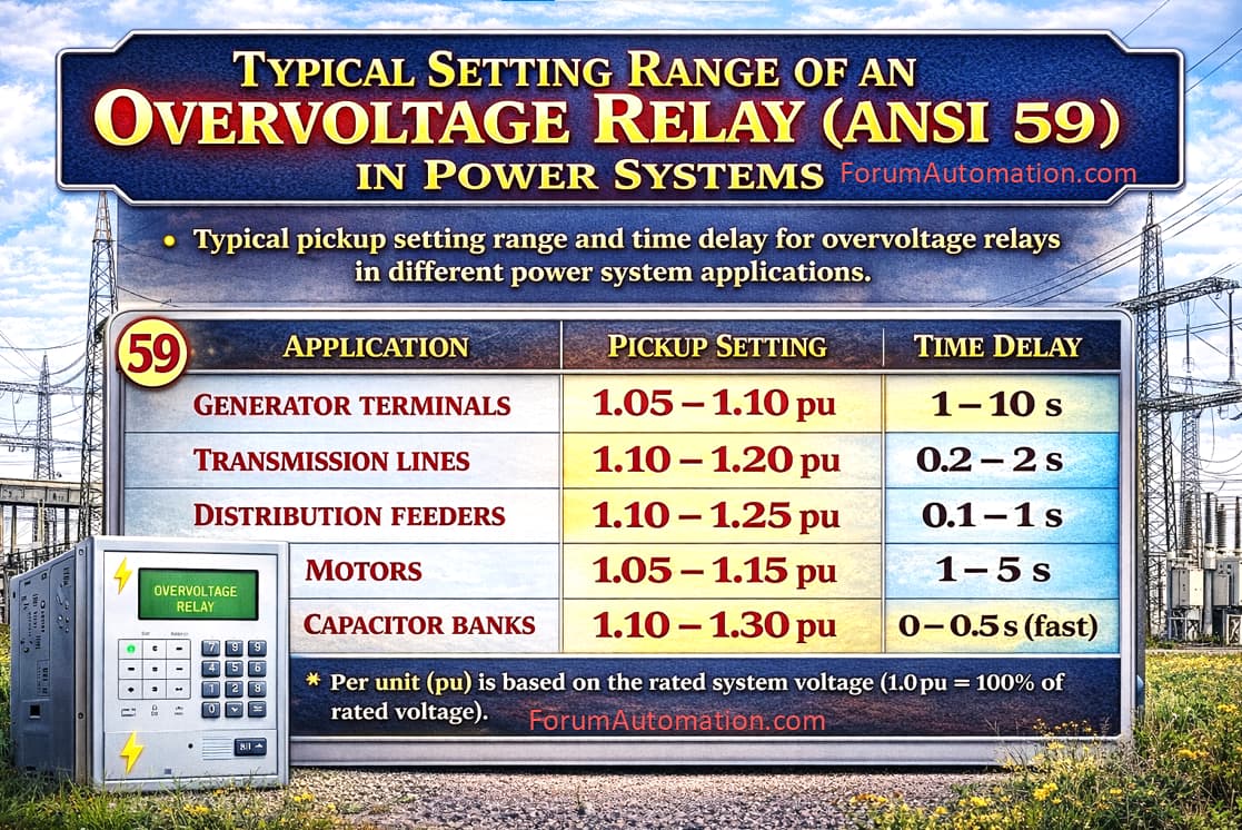
| Application Area | Pickup Setting (per unit) | Time Delay |
|---|---|---|
| Generator terminals | 1.05 - 1.10 pu | 1 - 10 s |
| Transmission lines | 1.10 - 1.20 pu | 0.2 - 2 s |
| Distribution feeders | 1.10 - 1.25 pu | 0.1 - 1 s |
| Motors | 1.05 - 1.15 pu | 1 - 5 s |
| Capacitor banks | 1.10 - 1.30 pu | 0 - 0.5 s (fast) |
Per unit (pu) is based on rated system voltage (1.0 pu = 100% rated voltage).
Practical Example
For an 11 kV system:
1.10 pu = 12.1 kV
1.20 pu = 13.2 kV
So the overvoltage relay may be set to trip between 12.1 kV and 13.2 kV depending on the protection methods.
Why not set too low?
To avoid nuisance tripping due to the normal voltage fluctuations.
To allow AVR tap changes and system transients.
Why not set too high?
Used to prevent insulation stress.
To protect equipment (transformers, motors, surge arresters).
You can also follow us on AutomationForum.co, Facebook and Linkedin to receive daily Instrumentation updates.
You can also follow us on ForumElectrical.com , Facebook and Linkedin to receive daily Electrical updates.