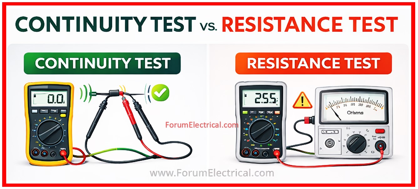
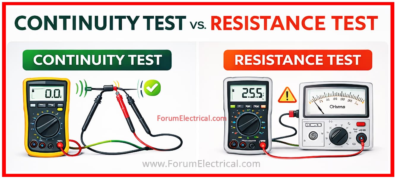
Here is a clear comparison table between Continuity Test and Resistance Test utilized in electrical testing:
| Parameters | Continuity Test | Resistance Test |
|---|---|---|
| Definition | Checks whether a complete electrical path exists (open or closed circuit). | Measures the exact opposition to current flow in ohms (Ω). |
| Purpose | To verify circuit continuity (no break in wire or connection). | To measure the resistance value of a component, conductor, or circuit. |
| Output Result | Gives indication as Beep / No Beep, or 0 / OL. | Gives numerical value in Ohms (Ω), kΩ, or MΩ. |
| Accuracy | Qualitative test (only confirms presence or absence of continuity). | Quantitative test (provides exact resistance value). |
| Test Voltage | Very low voltage (typically 2–5 V from multimeter). | Slightly higher but still low voltage from multimeter test circuit. |
| Measurement Range | Used for very low resistance (typically 0–50 Ω). | Used for wide range (from milliohms to megaohms depending on instrument). |
| Indication Method | Audible beep and visual indication. | Numerical display only. |
| Instrument Used | Multimeter in continuity mode. | Multimeter, Micro-ohmmeter, or Ohmmeter. |
| Main Application | Checking wires, fuses, switches, and connections. | Measuring resistor value, winding resistance, cable resistance. |
| Decision Type | Pass/Fail test. | Analytical measurement. |
| Example | Checking if a cable is broken or intact. | Measuring motor winding resistance (e.g., 2.5 Ω). |
| Speed | Faster test. | Slightly slower due to measurement calculation. |
You can also follow us on AutomationForum.co, Facebook and Linkedin to receive daily Instrumentation updates.
You can also follow us on ForumElectrical.com , Facebook and Linkedin to receive daily Electrical updates.