The operation of a synchronous generator (also called an alternator) is based on the principle of electromagnetic induction AND when a conductor moves in a magnetic field, an EMF (voltage) is induced.
Basic Working Principle
A synchronous generator converts mechanical energy → electrical energy.
It works according to Faraday’s Law of Electromagnetic Induction, which states that a changing magnetic flux induces an electromotive force (EMF).
Parts of a Synchronous Generator
1). Rotor (Field System)
Rotating part of the generator
Produces a magnetic field
Excited using DC supply
Types:
Salient pole (low-speed machines)
Cylindrical rotor (high-speed turbines)
2). Stator (Armature)
Stationary part
Contains three-phase armature windings
Where output voltage is generated
How it Works?
DC excitation is applied to the rotor winding → creates a magnetic field
A prime mover (like a turbine or engine) rotates the rotor
The rotating magnetic field cuts across the stator conductors
According to electromagnetic induction, an AC voltage is induced in stator windings.
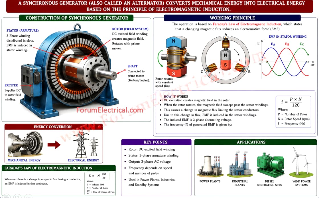
The output is typically three-phase AC power
Key Feature: Synchronous Speed
The rotor rotates at a constant speed called synchronous speed, given by:
Ns=120f/P
Where
f = frequency (Hz)
P = number of poles
This constant speed is called a synchronous generator.
Important Characteristics
- Produces constant frequency voltage
- Rotor speed is synchronized with output frequency
Widely used in:
- Power plants (hydro, thermal, nuclear).
- Large-scale electricity generation.