What is Switch De-bouncing?
When a mechanical switch is pressed, the transition from OFF to ON is not perfectly smooth. Because of the internal metal contacts, the signal briefly oscillates between ON and OFF for a few milliseconds. This phenomenon is known as “bouncing.” Since a microcontroller (MCU) works at very high speed, it may interpret these rapid fluctuations as multiple presses instead of a single action.
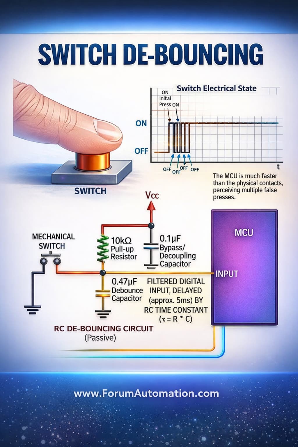
The waveform illustrates this behavior clearly. Rather than a clean step change, the signal jitters several times before becoming stable. If this is not corrected, it can lead to issues in digital circuits such as false triggering or unintended multiple counts.
To overcome this problem, an RC debouncing circuit is applied. A pull-up resistor (10 kΩ) ensures the input remains HIGH when the switch is not pressed. When the switch is activated, the capacitor (0.47 µF) charges or discharges gradually, preventing abrupt voltage changes.
Here, the capacitor behaves like a filter, suppressing fast variations and allowing only a smooth transition to reach the MCU input. The delay introduced is determined by the RC time constant (τ = R × C), which typically falls in the range of a few milliseconds.
In addition, the 0.1 µF capacitor connected near Vcc serves as a decoupling capacitor, reducing electrical noise and maintaining circuit stability.
As a result, the MCU receives a single clean signal transition, ensuring accurate and reliable switch operation in digital systems.