What is scaling block in PLC?
What is a scaling block in PLC?
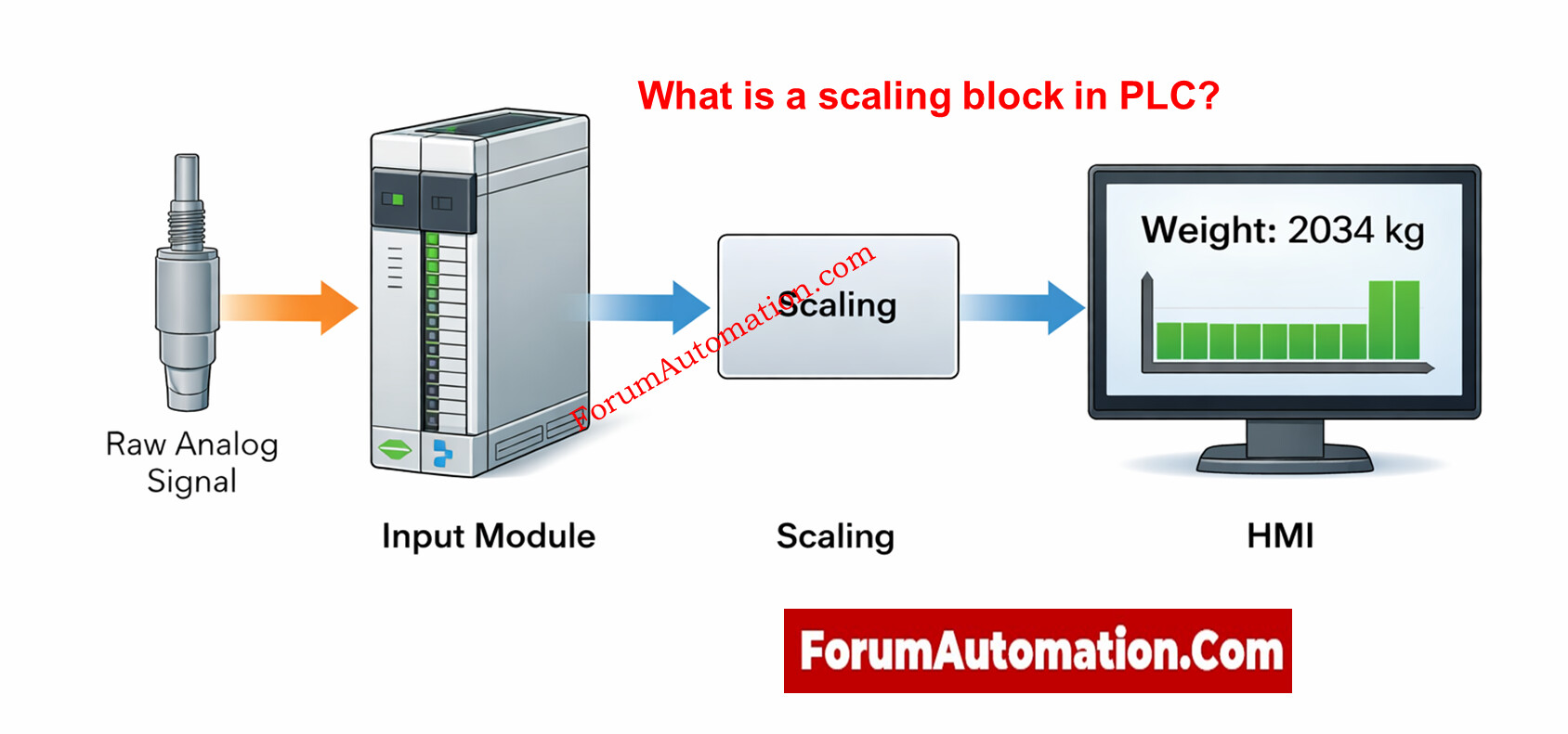
A scaling block in a PLC is a basic programming tool that changes raw input signals into useful engineering units. Most analog input modules read values as raw counts or whole numbers that come from signals like 4–20 mA or 0–10 V. A scaling block changes these raw statistics into values that operators and control logic can understand, such temperature, pressure, level, or flow.
For example, a pressure transmitter might send a signal of 4–20 mA that means 0–100 bar. This is not something that the PLC knows on its own. Using a linear equation, the scaling block translates the raw input range to the engineering range that goes with it. After scaling, the value can be used for PID control, alarms, interlocks, and HMI displays without fail.
It is good programming practice to put scaling blocks close to the I/O layer so that all downstream logic works in engineering units. Advanced scaling blocks have capabilities like checking ranges, finding values that are out of range, alert flags, and stopping divide-by-zero errors. Some also have filtration or square-root extraction for flow applications. To minimize rounding mistakes or overflow problems, it’s very important to use the same data types all the time (usually REAL).
Scaling blocks make code easier to read, fix problems faster, and keep it up to date over time. Without the right scale, alarms that go off at the wrong time, control loops that don’t work, and operator displays that aren’t clear are all common problems. Scaling block discussions get a lot of attention on forums since a lot of commissioning problems in the real world are caused by wrong scaling settings instead of hardware concerns.