What is a HAC drawing?
What is a HAC Drawing?
Definition
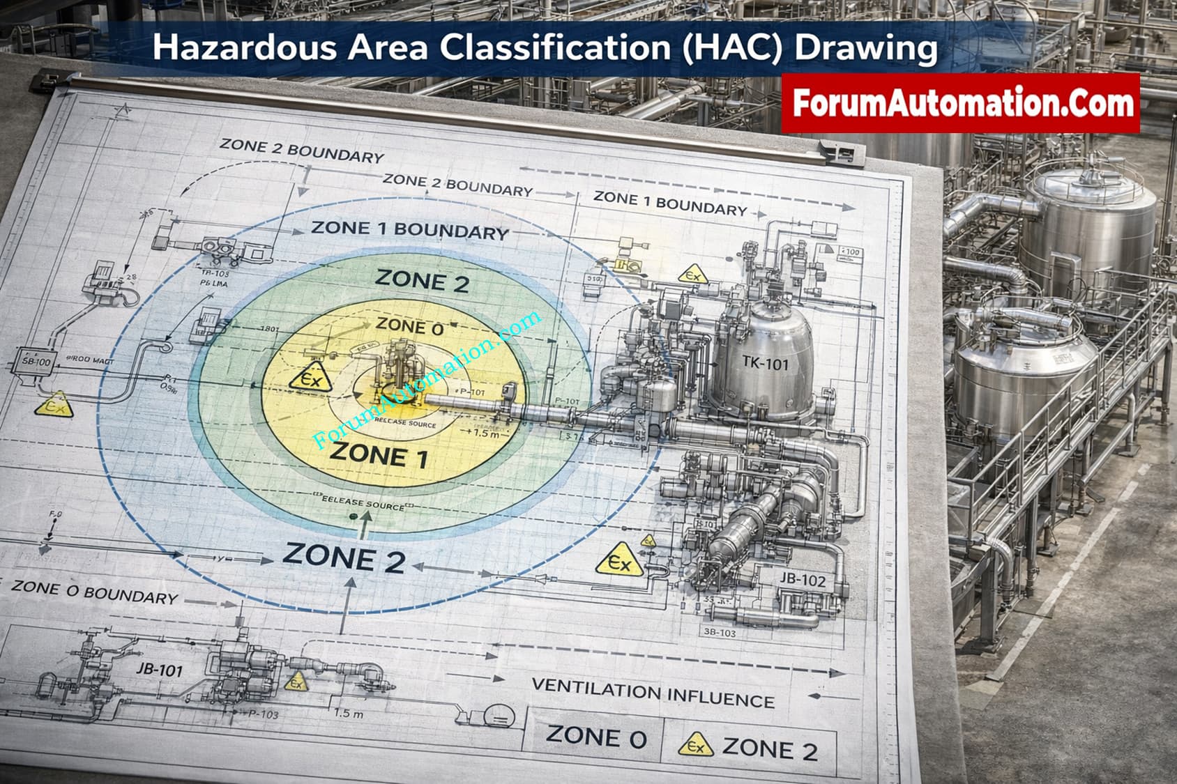
A Hazardous Area Classification (HAC) drawing is a comprehensive engineering document that shows where hazardous areas are in a facility and how big they are. This helps engineers choose safe equipment and stay away from fire hazards.
What a HAC Drawing Includes
- Zone categorization (Zone 0/1/2 and 20/21/22)
- 2D/3D size of dangerous locations (height, radius)
- Where it comes from (valves, flanges, vents, pumps)
- Layout of process equipment, such as tanks, compressors, and pipes
- Conditions for ventilation and patterns of dispersion
How It Is Developed
Based on:
- P&ID and plot plan
- Process data (pressure, temperature, flow)
- Material properties (LEL, flash point)
- Release scenarios and frequency
Requires collaboration between process, instrumentation, and safety teams
Practical Engineering Application
Used during FEED, detailed design, and commissioning
Critical input for selecting:
- Explosion-proof (Ex d) or intrinsically safe (Ex i) instruments
- Cable routing and gland types
- Junction boxes and control panels
Field Example
Tank farm scenario:
- Inside tank → Zone 0
- Around vent nozzle → Zone 1
- Peripheral area → Zone 2
Why It Is Critical
- Prevents installation of ignition sources
- Ensures compliance with ATEX, IEC, API standards
- Supports HAZOP, SIL, and safety audits
Common Issues
- Outdated drawings after plant modification
- Misalignment with actual installation
- Over-classification increasing project cost
Engineering Tip
Always cross-check HAC drawings with site conditions real leak points often differ from design assumptions.