What Are the Essential Components of a Motor Control Panel?
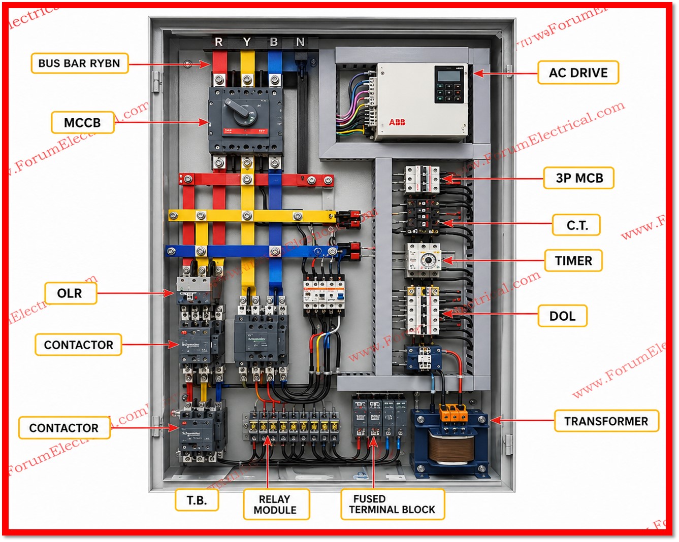
Reference Image Provided by the Respondent
Reference Image Provided by the Respondent
A motor control panel integrates key electrical components to ensure safe, efficient, and reliable motor operation in industrial automation systems. It typically includes an MCCB, busbars, AC drive (VFD), contactors, overload relay (OLR), timer, current transformers (CTs), control transformer, relay modules, and terminal blocks, each performing a specific function in motor protection, control, and power distribution.
Protects the motor control panel from overloads and short circuits while providing safe manual isolation during maintenance.
Copper or aluminum conductors that distribute electrical power efficiently to different devices within the panel.
Controls the speed and torque of AC motors by varying the supply voltage and frequency, improving energy efficiency and process control.
An electrically operated switch that starts and stops the motor remotely based on control signals.
Protects the motor from overheating by disconnecting the circuit when excessive current flows for an extended period.
Provides adjustable time delays for motor starting, stopping, sequencing, or changeover operations in control circuits.
Reduces high current to a standard low value for accurate current measurement, monitoring, and protective relays.
Steps down the incoming voltage to a lower control voltage required for relays, contactors, and other control devices.
Interface devices that switch control circuits, provide electrical isolation, and perform logic or protection functions.
Provide secure and organized connection points for field wiring, making installation, troubleshooting, and maintenance easier.
Low-voltage wiring that interconnects all control components and carries signals for motor operation and protection.
Heavy-duty conductors that carry electrical power from the supply to the motor and other power devices within the panel.
Organizes and protects electrical wiring inside the panel, ensuring a neat layout and easier maintenance.
Maintains proper internal temperature by circulating air and preventing dust from entering the control panel.
Provides a common grounding point for all metallic parts, improving personnel safety and ensuring proper fault current flow.
Allow operators to start, stop, reset, and monitor the motor through illuminated indicators and control push buttons.
Enables operators to select different operating modes, such as Manual, Auto, or Local/Remote control.
Displays electrical parameters such as voltage, current, frequency, power, and energy for system monitoring.
Executes automation logic and controls motor operation based on programmed sequences and input signals.
Provides a graphical interface for operators to monitor system status, adjust settings, and control the motor system.