What is Megger?
A megger (megohmmeter) is a type of electrical device that measures the insulation resistance (IR) between conductors & the ground.
It works by supplying a high DC voltage (usually 250 V to 5000 V) and measuring the associated leakage current.
Working Principle
A high DC voltage is placed between the conductor & the earth.
The leakage current via the insulation is measured.
The megger computes insulating resistance using:
R= V/I
The result is shown on the analog dial (or) digital screen.
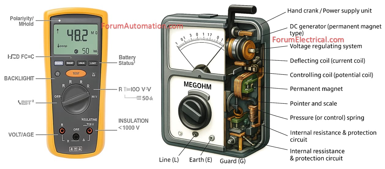
Key Features of a Megger Device
| Component | Description / Function |
|---|---|
| 1. Hand Crank / Power Supply Unit | Older meggers use a manual hand crank generator to produce DC voltage. Modern digital meggers use battery or mains-powered DC voltage sources (typically 250 V to 1000 V). |
| 2. DC Generator (Permanent Magnet Type) | Converts mechanical energy (from crank) into DC voltage needed for insulation testing. Usually generates voltages from 500 V to 2500 V depending on design. |
| 3. Voltage Regulating System | Maintains constant output voltage under varying load conditions, ensuring accurate test readings. |
| 4. Deflecting Coil (Current Coil) | Carries the current flowing through the insulation under test; produces torque proportional to leakage current. |
| 5. Controlling Coil (Potential Coil) | Connected across the generator output; produces torque proportional to the applied voltage. |
| 6. Permanent Magnet | Creates a uniform magnetic field in which the coils operate, ensuring stable and precise pointer movement. |
| 7. Pointer and Scale (Dial Display) | The pointer indicates the insulation resistance directly on a logarithmic scale (typically from 0.1 MΩ to 1000 MΩ). |
| 8. Pressure (or Control) Spring | Provides controlling torque to balance the magnetic torques, allowing the pointer to return to zero when not in use. |
| 9. Test Terminals / Probes | Usually three terminals are provided: |
| • Line (L) – connected to the conductor under test. | |
| • Earth (E) – connected to earth or ground. | |
| • Guard (G) – used to eliminate surface leakage currents. | |
| 10. Internal Resistance & Protection Circuit | Limits current output to protect both the instrument and the insulation under test from damage. |
| 11. Digital Display (in Electronic Megger) | Modern digital meggers have an LCD/LED display that shows insulation resistance, test voltage, and other parameters numerically. |
| 12. Control Buttons / Selector Switches | For range selection (250 V, 500 V, 1000 V), test duration, and test mode (IR, PI, DAR, etc.). |
| 13. Battery (for Digital Models) | Rechargeable lithium or NiMH batteries supply energy for test voltage generation. |
| 14. Microcontroller / Processing Circuit | In digital models, this converts analog current and voltage readings into accurate resistance values using Ohm’s law ( R = V/I ). |
You can also follow us on AutomationForum.co, Facebook and Linkedin to receive daily Instrumentation updates.
You can also follow us on ForumElectrical.com , Facebook and Linkedin to receive daily Electrical updates.