What are control loops in a P&ID?
What are control loops in a P&ID?
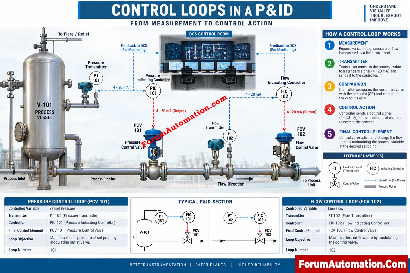
In a P&ID, control loops are graphical depictions that illustrate how a process variable is measured, compared to a target value, and adjusted. A control loop contains a measuring element, transmitter, controller and final control element such as a control valve.
How a Control Loop Works
Suppose a flow control loop. The process flow is measured using a flow element. The flow transmitter transmits a signal to the controller showing flow. The controller compares the observed flow to the setpoint and calculates an output. That output powers a control valve to increase or reduce the flow rate.
Engineers tag the loop using instrument tags on a P&ID. The loop number is common to instruments and makes tracing of a control function easy. Signal lines are electrical or digital communication routes.
What Engineers Should Check
When reading a control loop on a P&ID, verify:
- Process variable and tag
- Transmitter and controller functions
- Signal direction and signal type
- Final control element and fail position
- Controller action and philosophy
- Alarm, interlock, or shutdown relationships
For example, PT, PIC and PCV can constitute a pressure control loop from the pressure measurement, via the controller action, to the valve manipulation.
Practical Plant Use
Instrumentation Engineers use control loops to understand the design purpose before installation, commissioning and troubleshooting. During commissioning, P&ID is compared with loop diagram, instrument index, I/O list and control narrative. A mismatch might lead to inappropriate wiring, inaccurate DCS design or improper valve action.
Control loops in P&ID designs are very important to understand in relation to operation, loop checking, maintenance and troubleshooting.