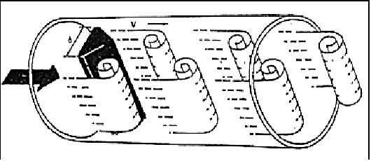
When a fluid moves with high Reynolds number past a stationary object (a “bluff body”), there is a tendency for the fluid to form vortices on either side of the object. Each vortex will form, then detach from the object and continue to move with the flowing gas or liquid, one side at a time in alternating fashion. This phenomenon is known as vortex shedding, and the pattern of moving vortices carried downstream of the stationary object is known as a vortex street
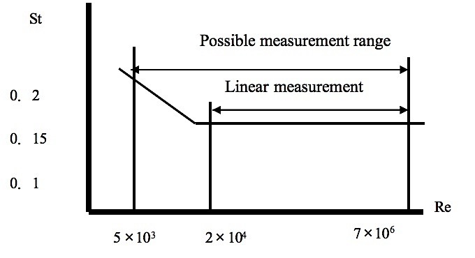
The distance between successive vortices downstream of the stationary object is relatively constant, and directly proportional to the width of the object, for a wide range of Reynolds number values37. If we view these vortices as crests of a continuous wave, the distance between vortices may be represented by the symbol “lambda”.

If a differential pressure sensor is installed immediately downstream of the stationary object in such an orientation that it detects the passing vortices as pressure variations, an alternating signal will be detected.
The frequency of this alternating pressure signal is directly proportional to fluid velocity past the object, since the wavelength is constant. This follows the classic frequency-velocity-wavelength formula common to all traveling waves (λf = v).

Since we know the wavelength will be equal to the bluff body’s width divided by the Strouhal number (approximately 0.17), we may substitute this into the frequency-velocity-wavelength formula to solve for fluid velocity (v) in terms of signal frequency (f) and bluff body width (d).
Thus, a stationary object and pressure sensor installed in the middle of a pipe section constitute a form of flowmeter called a vortex flowmeter. Like a turbine flowmeter with an electronic “pickup” sensor to detect the passage of rotating turbine blades, the output frequency of a vortex flowmeter is linearly proportional to volumetric flow rate.