[color=#CF2E2E] VFD Primary Components [/color]
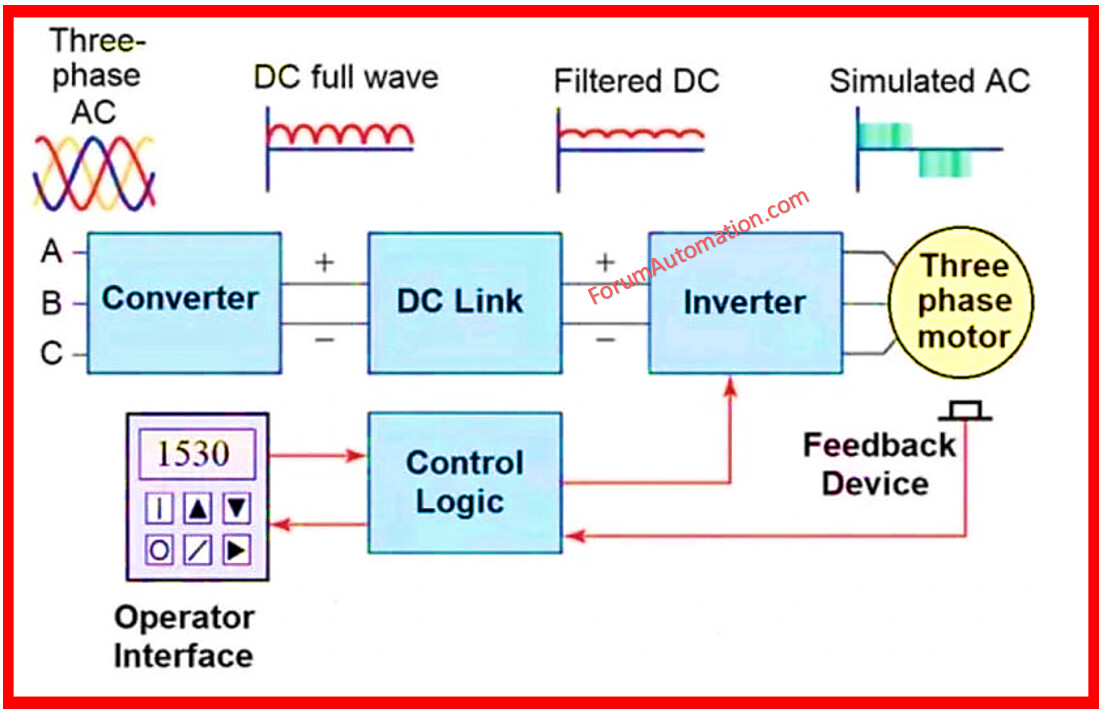
A typical [url= VFD Installation Procedure][color=#1E00A3] Variable Frequency Drive (VFD) [/color][/url] has three fundamental components that convert and manage electrical power:
1). Rectifier
2). DC Link (Intermediary Circuit)
3). Inverter
4). Controller
[color=#CF2E2E] 1). Rectifier [/color]
This part converts the input AC voltage to DC. It is often manufactured with diodes (or) thyristors.
[color=#CF2E2E] 2). DC Link (Intermediary Circuit) [/color]
This section, located between the rectifier & the inverter, uses capacitors to store and smooth DC electricity. It also helps to reduce voltage ripples.
[color=#CF2E2E] 3). Inverter [/color]
This is the heart of VFD. It employs power transistors (such as IGBTs) to convert the DC voltage into an AC voltage with adjustable frequency and voltage.
[color=#CF2E2E] 4). Controller [/color]
This functions as the system’s brain. It interprets control inputs (such as speed commands) and transmits precise signals to the inverter. Control methods like PWM (Pulse Width Modulation) are used here.
Understanding these components aids in selecting the appropriate drive, identifying issues, and improving operation & maintenance accuracy.
You can also follow us on [color=#ff7700]AutomationForum.co[/color], [url= https://www.facebook.com/instrumentation.control][color=#1E00A3]Facebook[/color][/url] and [url= https://www.linkedin.com/showcase/81532759/feed/posts/][color=#1E00A3]Linkedin[/color][/url] to receive daily Instrumentation updates.
You can also follow us on [color=#ff7700] ForumElectrical.com [/color], [color=#1E00A3] Facebook [/color] and [color=#1E00A3] Linkedin[/color] to receive daily Electrical updates.