VFD Control & Motor Wiring (1-Phase Input to 3-Phase Output)
A practical VFD wiring configuration for a 3-phase induction motor based on the official installation guide, showing how to operate a three-phase motor from a 220V single-phase input supply.
This wiring setup includes:
-
220V single-phase input on R/L1 and S/L2
-
Forward and Reverse control using FWD/REV
-
Start and Stop push-button wiring
-
Speed control using a potentiometer connected to +10V, AVI, and ACM
-
Optional braking resistor connection through BR/BUE
-
Three-phase motor output on U, V, and W
-
Multi-function relay output RA, RB, and RC for fault indication
-
Control terminals MI1 to MI6 with DCM as the digital signal common.
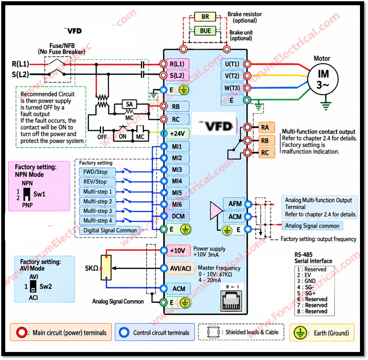
This VFD is designed for 220V single-phase input, and the correct control terminal names are MI1 to MI6, not M0 to M2.
This type of VFD wiring is widely used in industrial automation where only single-phase power is available but precise speed control of a three-phase motor is required.
Understanding proper VFD connections helps ensure safe installation, reliable operation, and effective troubleshooting.