During transformer differential protection testing especially under single-phase-to-earth faults engineers may observe an important behavior in phase-selective differential relays:
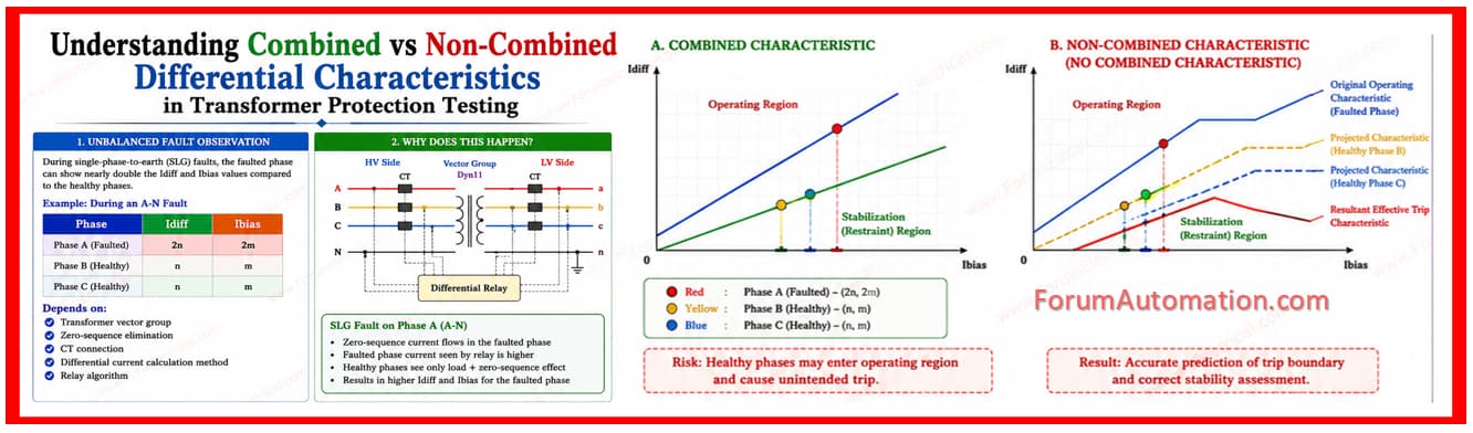
The faulted phase can show nearly double the Idiff and Ibias values compared to the healthy phases.
For example during an A-N fault:
Phase A → Idiff = 2n, Ibias = 2m
Phase B → Idiff = n, Ibias = m
Phase C → Idiff = n, Ibias = m
This occurs depending on:
Transformer vector group
Zero-Sequence Elimination
CT connection
Differential current calculation method
Relay algorithm
Many modern relays use phase-selective measurement with OR-linked tripping logic.
This means that even if the faulted phase remains inside the restraint/stabilization region, the healthy phase measuring elements may unintentionally enter the operating region and issue a trip.
To handle this, advanced relays provide logic handling for:
- Combined characteristic
- Non-combined characteristic
In OMICRON Test Universe, selecting “No Combined Characteristic” allows the software to automatically project the effective characteristics seen by all three phase measuring elements.
The software overlays:
- Original operating characteristic
- Projected characteristic from healthy phases
- Resultant effective trip characteristic
This helps engineers correctly evaluate:
- Relay stability
- Trip behavior
Pass/fail assessment during transformer differential testing
A very important concept for protection engineers working on:
- Transformer differential schemes
- REF and biased differential protection
- Relay testing & commissioning
- OMICRON advanced testing
Understanding how the relay internally interprets Idiff and Ibias during unbalanced faults is critical for avoiding false interpretations during commissioning and troubleshooting.