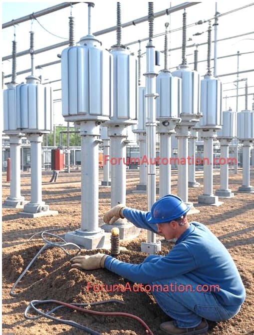
Types of Neutral Earthing
Neutral earthing (or grounding) is the process of connecting the neutral point of a generator, transformer (or) distribution system to ground. This is done to assure system safety, equipment protection & employee security. Earthing methods are chosen based on system voltage, equipment rating & fault protection needs.
The following are the primary types of neutral earthing utilized in electrical systems:
1). Solid Earthing
2). Resistance Earthing
3). Reactance Earthing
4). Peterson Coil Earthing (Resonant Earthing)
5). Isolated (Unearthed) Neutral System
1). Solid Earthing
Solid earthing connects the neutral point directly to the ground, with no resistance or reactance. This guarantees that during a fault, the fault current is sufficient to activate protection devices (such as circuit breakers and relays) immediately.
Advantages: Fast fault resolution and simple design.
Disadvantages: If a high fault current is not discharged immediately, it can harm equipment.
Applications: Widely employed in low-voltage distribution networks & high-voltage transmission systems.
2). Resistance Earthing
The neutral is connected to ground via a resistor. This keeps the fault current at a safe level while allowing protective relays to detect & remove the fault. Resistance earthing can be further classified into:
Advantages: Low resistance earthing allows for increased fault current and facilitates quick fault detection.
Disadvantages: High Resistance Earthing: Reduces fault current to an extremely low level, limiting damage but necessitating delicate relays.
Applications: Utilized in medium-voltage systems (3.3 to 33 kV) to manage fault current.
3). Reactance Earthing
In reactance earthing, the neutral is connected to the earth via a reactor (inductor). This reduces the fault current through the use of inductive reactance along the fault path.
Advantages: Controls fault current more efficiently than resistance.
Disadvantages: If not correctly built, can result in excessive transient overvoltage.
Applications: Applications include systems where resistance earthing is impractical yet current restriction is still required.
4). Peterson Coil Earthing (Resonant Earthing)
In this manner, the neutral is grounded using a Peterson coil (arc suppression coil) that is an adjustable inductor designed to negate the system’s capacitive charging current. This reduces the fault current over a single line-to-ground fault & avoids arcing.
Advantages: Reduces arc flash dangers and increases system reliability.
Disadvantages: Complex design and expensive price.
Applications: Commonly utilized in high-voltage transmission & distribution networks, particularly in systems with lengthy overhead lines.
5). Isolated (Unearthed) Neutral System
In this setup, the neutral is not wired to ground. Instead, the system floats above Earth’s potential. A single line-to-ground failure affects only the problematic phase, while the rest of the system can function normally.
Advantages: Supply continuity even in the presence of a single line-to-ground fault.
Disadvantages: Capacitive coupling can cause overvoltages, and fault identification is difficult.
Applications: Utilized in small industrial networks, control systems & some high-voltage applications where uninterrupted power is required.
Neutral earthing ensures electrical safety & system stability. Choosing the appropriate earthing method is important for equipment protection, personnel safety & ensuring an uninterrupted supply.
You can also follow us on AutomationForum.co, Facebook and Linkedin to receive daily Instrumentation updates.
You can also follow us on ForumElectrical.com , Facebook and Linkedin to receive daily Electrical updates.
