Transformer Winding Resistance Test
Reliable transformer operation begins with verifying the health of its windings. The Winding Resistance Test plays a key role in ensuring electrical and mechanical integrity before energization and during periodic maintenance.
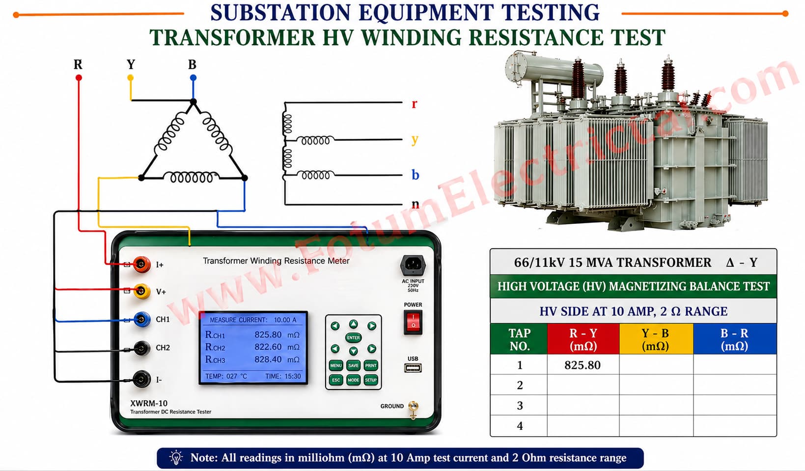
This test includes applying a controlled DC current to the transformer windings and measuring the voltage drop.
Consistent and accurate winding resistance values ensure efficient current flow, reduced losses, and reliable long term performance.
This test is a foundation step in transformer reliability and is performed during factory acceptance, commissioning, and routine diagnosis.
Required Equipment
Digital resistance meter or DC winding resistance tester
Test leads with Kelvin (four wire) connection Temperature measuring device (thermometer or RTD input)
Safety PPE
Precautions Before Testing:
Transformer must be fully de energized and isolated
Discharge all windings to remove residual magnetism
Ensure no trapped charge in bushings
Record ambient and oil temperature
Test Procedure
Step 1: Verify Test Setup
Identify transformer terminals for HV winding and LV winding.
Ensure correct test range on the resistance tester.
Step 2: Connect Test Leads
Use Kelvin four terminal method
(2 leads for current injection, 2 for voltage sensing).
Connection layout
Primary side: Connect to bushings (A, B, C or H1, H2, H3)
Secondary side: connect (a, b, c or X1, X2, X3)
Step 3: Stabilize and Apply DC Current
Start the tester and apply a controlled DC current.
Allow reading to stabilize because inductance delays steady state.
For large transformers stabilization may take several minutes.
Step 4: Measure and Record Readings
Record resistance values for each phase and tap.
Step 5: Repeat for Other Tap Positions For OLTC (On Load Tap Changer) transformers Record values for every tap position to detect contact resistance issues.
Step 6: Correct Readings for Temperature Transformer resistance varies with temperature. Standard temperature correction formula R2 = R₁x (T2+234.5) (T₁ + 234.5) Where
R₁ = measured resistance
T₁ = measured temperature
T₂ = reference temperature (usually 20°C)
Step 7: Compare With Reference Data Compare values with previous records and manufacturer tolerances.
Normal variation range between phases should be small.
Large deviations indicate potential issues such as Loose joints, Damaged windings, Tap changer contact faults.
Step 8: Discharge the Winding
After the test, allow winding to discharge until voltage reaches zero.
Never disconnect leads immediately because inductive windings store energy.
Acceptance Criteria
Phase resistance imbalance must be within acceptable tolerance.
No abnormal increase vs previous test history.
Smooth resistance variation across tap changer positions.