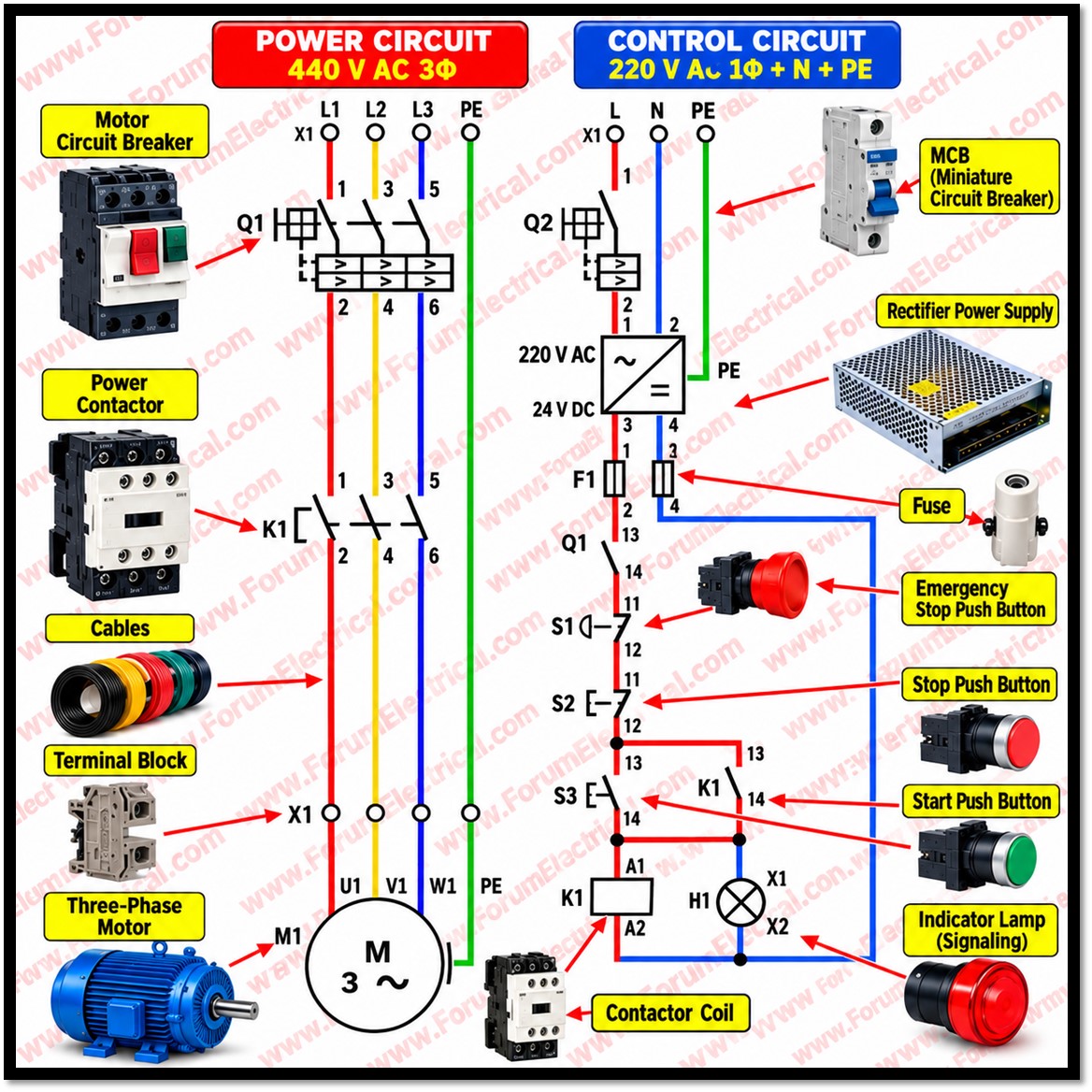
Three-Phase Motor Power and Control Circuit
A three-phase motor control system integrates the power circuit, control circuit, and auxiliary DC supply to provide reliable motor operation, electrical protection, and operational safety.
The industrial electrical schematic includes the following components:
- Three-Phase Power Circuit: 440 V AC supply, three-pole circuit breaker, contactor main contacts, thermal overload relay, and three-phase induction motor.
- Control Circuit: 220 V AC control supply with control-circuit protection, START push button (NO), STOP push button (NC), emergency-stop contact (NC), contactor coil, and auxiliary holding contact (NO).
- 24 V DC Power Supply: AC-to-DC switched-mode power supply for compatible sensors, PLC inputs, relays, or other control devices.
- Motor Protection: Short-circuit protection through a suitably rated circuit breaker or fuses, and overload protection through a correctly selected thermal overload relay.
- Indication and Status Monitoring: Pilot lamps for power availability, motor running status, and overload trip indication, using appropriate auxiliary contacts and control voltages.
- Protective Earthing: Protective earth (PE) connection to the motor frame and conductive electrical enclosure for fault protection.
- Electrical Panel Wiring: Clear separation and identification of power wiring, AC control wiring, and 24 V DC control wiring, with suitable terminals, cable sizing, and insulation ratings. The contactor’s auxiliary NO contact provides the seal-in function after the START push button is released. The STOP and emergency-stop contacts interrupt the contactor coil circuit to stop the motor. Where a risk assessment requires a safety-related emergency-stop function, an appropriately designed safety relay or safety controller may be necessary.