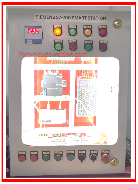
This is a Siemens S7-200 Smart PLC-based control panel designed for automation applications. It integrates various input devices (like push buttons), output indicators (pilot lights), communication modules, and power supply components to control and monitor industrial processes.
This control panel is designed for industrial automation, integrating manual control, monitoring, protection, and communication in one compact unit.
1). PLC – Siemens S7-200 Smart
The brain of the system, executing the control logic programmed by the user.
Supports Modbus communication and Ethernet (TCP/IP).
Handles both digital inputs (I0.x) and digital outputs (Q0.x).
Interfaces with sensors, actuators, and communication devices.
2). Inputs – NOPB & NCPB
NOPB (Normally Open Push Button) and NCPB (Normally Closed Push Button) are used for manual control.
Labeled I0.0 to I0.7 at the bottom of the panel.
3). Outputs – Pilot Lights
Labeled Q0.0 to Q0.7 at the top of the panel.
Show system status, alarms, or process states.
Controlled by PLC output channels.
4). Power Supply – SMPS
Switch Mode Power Supply (SMPS) converts 230V AC to 24V DC to power the PLC and control devices.
Compact and efficient, ensuring stable voltage for automation components.
5). Communication – Network Switch
Connects the PLC to other devices via Ethernet.
Allows programming, data exchange, and monitoring over a TCP/IP network.
Facilitates Modbus TCP/IP protocol communication with HMIs, SCADA, or other PLCs.
6). Relays & Relay Channels
Used to interface PLC outputs with high-power devices.
Relay channel ensures electrical isolation between PLC’s low-voltage outputs and high-voltage load circuits.
7). Terminal Blocks
Neatly terminate and organize wiring.
Provide connection points for inputs, outputs, and power.
8). MCB – Miniature Circuit Breaker
Protects the panel from short circuits and overloads.
Automatically cuts off power during a fault.
9). Energy Meter
Displays the supply voltage (here: 232V).
Monitors electrical parameters for energy management.
10). Selector Switch
Used for selecting modes (Auto/Manual, Local/Remote).
Sends input to PLC to change control modes.
11). Emergency Stop (E-Stop)
Red mushroom push button for immediate shutdown in case of emergency.
Interrupts control circuit power to stop all operations instantly.
12). Ethernet Cable
Connects PLC, network switch, and programming PC.
Supports high-speed data communication.
13). Modbus Communication
Modbus TCP/IP is implemented via Ethernet for industrial device communication.
PLC exchanges real-time process data with other devices like HMIs and SCADA.
You can also follow us on AutomationForum.co, Facebook and Linkedin to receive daily Instrumentation updates.
You can also follow us on ForumElectrical.com , Facebook and Linkedin to receive daily Electrical updates.