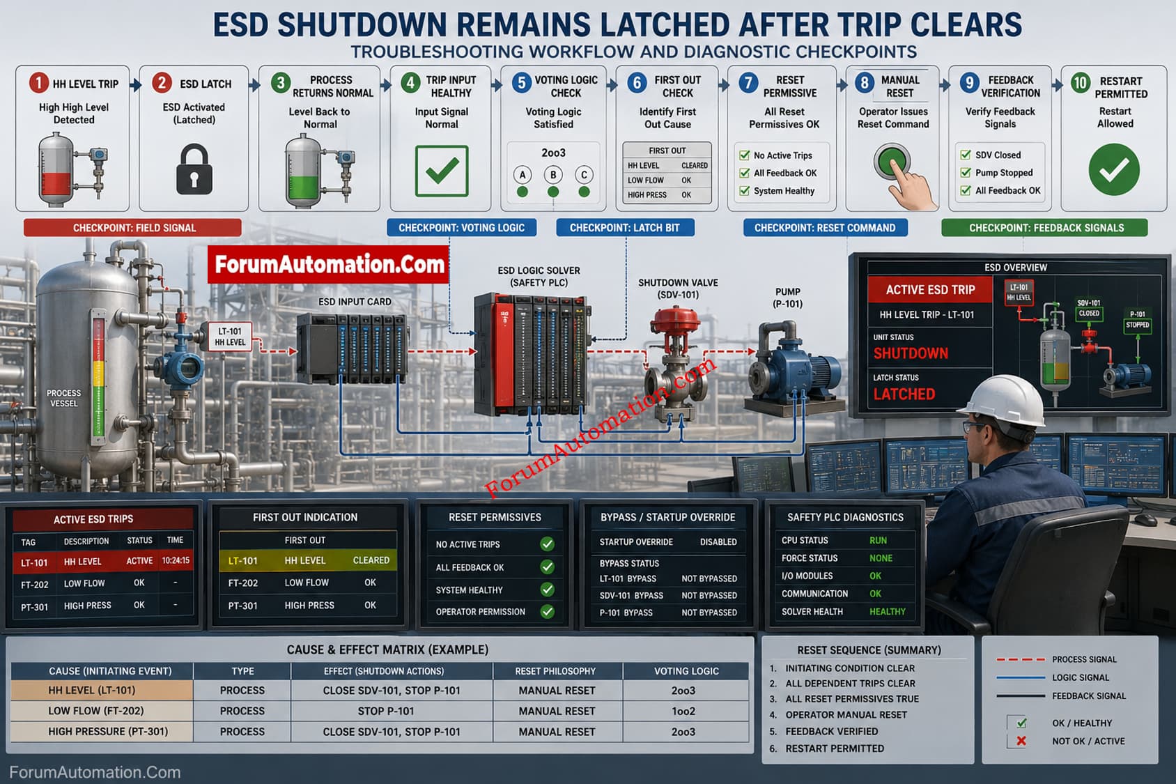
Process Unit Remains Shut Down Even After the Original ESD Trip Condition Has Cleared
An emergency shutdown is triggered by a high high level trip in a process vessel and normal plant operation is interrupted. The related pump is properly tripped and the shutdown valve is closed by the ESD system. When the process level is back to normal and the field transmitter shows a healthy reading, the operator tries to restart the unit. However, the ESD system remains latched, and the restart command is rejected even though the original trip condition is no longer present.
What could cause an ESD shutdown logic to remain active after the initiating trip condition has cleared? How should instrumentation and control engineers systematically check the latched trip logic, reset philosophy, Cause and Effect Matrix, field signal status, voting logic, manual reset command, reset permissives, bypass status, first out logic, PLC or safety logic solver diagnostics and feedback signals to identify why the ESD trip cannot be reset?
Process Unit Remains Shut Down Even After the Original ESD Trip Condition Has Cleared
Why the ESD Trip Remains Latched
An ESD shutdown is normally designed to remain in the safe state after the initiating condition disappears. A healthy transmitter alone does not prove that the reset chain is healthy. Many shutdown philosophies require the initiating cause to clear, followed by a manual reset, before restart is permitted.
Systematic Checks
- Verify the original HH level input at the ESD input card and confirm its healthy state.
- Check transmitter, switch, barrier, isolator, wiring, terminal and input diagnostics.
- Review voting logic, such as 1oo2 or 2oo3, for a remaining unhealthy channel.
- First check indicator to see what is the earliest active cause.
- Verify status of manual reset command, pushbutton operation and operator rights.
- Confirm reset permissives, startup overrides and approved bypass.
- Check shutdown valve, pump, motor and other feedback signals by the reset sequence.
- Trace the latched bit through the safety PLC or logic solver.
Do not force or bypass a safety trip simply to restore operation. Compare live logic with the approved Cause and Effect Matrix, shutdown philosophy and commissioning documents. The reset should occur only after the initiating cause, dependent trips and feedbacks are healthy. This prevents false resets and exposes cascade or permissive problems.
If the trip still remains, compare the operator reset command with reset input seen by the solver. Then trace each permissive backward until the first FALSE condition is found. This point usually provides the fastest route to the root cause.