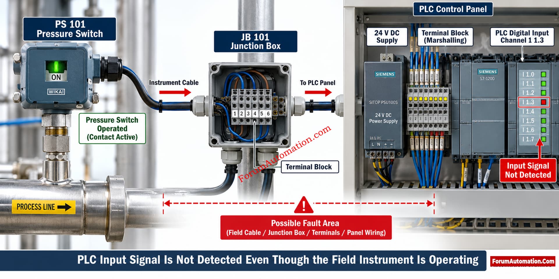
Don’t quickly jump to the conclusion that the problem is a bad PLC input module. The pressure switch contact is switching in the field but the PLC is not seeing the signal. The debugging should be done on the entire signal route from the field contact to the PLC input channel.
Most Likely Causes
The possible causes include incorrect PLC input wiring, loss of the required field supply voltage, incorrect common or return connection, a blown fuse, faulty interposing relay, incorrect terminal connection, damaged multicore cable, incorrect PLC channel mapping, or a failed PLC input channel.
Another possibility is that the field contact is changing mechanically but is not providing a reliable electrical signal because of contact resistance or an incorrect contact configuration.
What Should Be Checked First?
The first check is to measure the voltage directly at the PLC input terminals when the field device is in the ON state.
The engineer should check that the expected voltage is indeed present at the input channel of the PLC. This will immediately tell you if the fault is in the field wiring, the PLC hardware or the PLC settings.
If the correct voltage is present at the PLC input but the PLC diagnostic still shows the input as OFF, then inspect the input channel, the common connection, the channel settings or the PLC hardware.
If the voltage is absent, troubleshooting should move toward the field device, power supply, fuse, terminal connections, interposing relay, and cable.
Recommended Troubleshooting Sequence
- First verify the pressure switch contact operation with a multimeter.
- Check the voltage at the pressure switch terminals.
- Then check continuity through field cable and junction box terminals.
- Check terminal numbers according to authorized wiring diagram.
- If you have an interposing relay, check it out.
-
- Measure the voltage at the input terminal of the PLC.
- Check the PLC input common or return wiring is correct.
- Make that the PLC input channel is mapped correctly in the PLC program.
- Review PLC diagnostics for channel faults.
- Finally, test the input channel using a known good signal where permitted by the approved commissioning procedure.
Important Field Observation
A common troubleshooting mistake is to prove that the field instrument operates and then immediately conclude that the PLC input should also be ON.
The physical operation of the field device does not prove that the electrical signal has successfully reached the PLC.
The complete signal path must be verified:
Field device → Junction box → Cable → Marshalling or interposing relay → PLC terminal → PLC input channel → PLC logic
Practical Recommendation
Do not replace the PLC input module until the actual voltage at the PLC input terminal has been measured and the wiring, common, channel configuration, and intermediate components have been verified. A point to point signal check is normally the fastest way to isolate this type of fault.