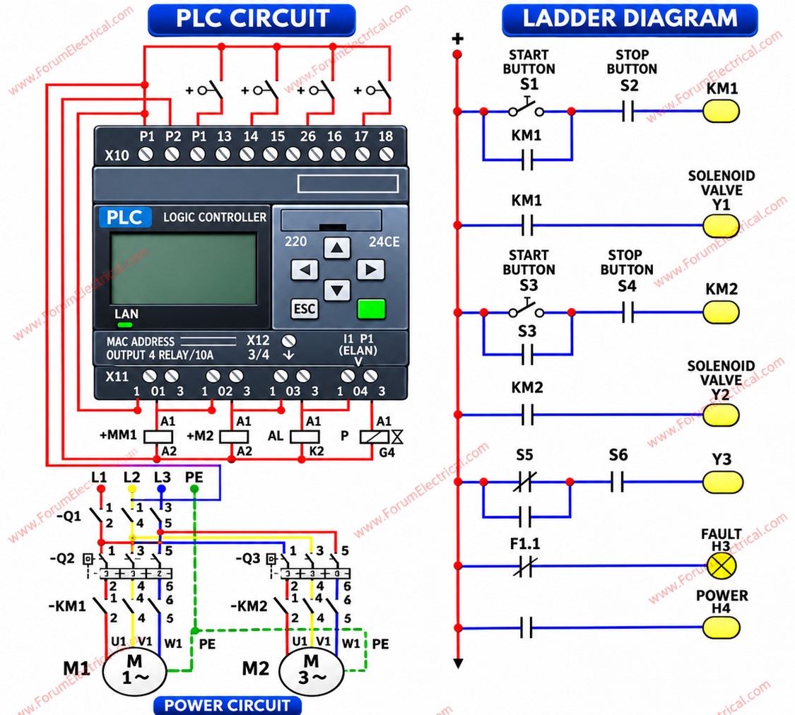
PLC Automation System: Wiring Diagram and Ladder Logic for Industrial Control
A comprehensive PLC automation schematic illustrating the integration of PLC hardware wiring and ladder logic programming for industrial control applications. The diagram covers motor control circuits, solenoid valve actuation, fault indication, and electrical power monitoring, demonstrating the coordination between field devices, PLC input/output modules, and control logic.