PLC Analog Input Troubleshooting
PLC Analog Input Shows an Incorrect Process Value Even Though the Field Transmitter Output Is Correct
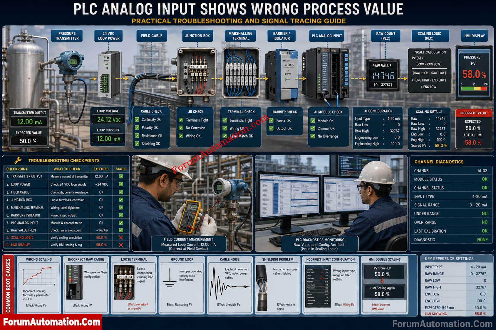
A critical process vessel is fitted with a pressure transmitter. The transmitter has been calibrated appropriately, and when checked at the transmitter terminals, it reads 12.00 mA. But the PLC analog input shows 58 percent instead of the expected scaled process value. The real process pressure is stable while the HMI trend has rapid fluctuation sometimes. The transmitter has been recalibrated, but the problem continues.
What could cause a PLC analog input to display an incorrect or unstable process value when the field transmitter output is correct? How should engineers troubleshoot the complete signal path, including field wiring, terminal connections, loop power supply, cable shielding, grounding, isolators, input card configuration, 4 to 20 mA scaling, raw counts, engineering range, filtering and PLC diagnostics to identify the actual root cause?
PLC Analog Input Troubleshooting
Trace the Signal Before Recalibrating
When a transmitter produces 4 to 20 mA correctly but the PLC shows an incorrect value, the transmitter should not be the first suspect. Trace the chain: transmitter, supply, cable, terminals, barrier or isolator, PLC analog input, raw value, scaling logic and HMI.
Systematic PLC Analog Input Checks
- Confirm transmitter output with a multimeter or loop calibrator. For a 4 to 20 mA range, 12 mA normally represents 50 percent.
- Measure current at marshalling and PLC terminals. A difference points toward wiring, termination, barrier or isolator problems.
- Check 24 VDC loop supply, polarity, cable continuity, loose terminals and resistance.
- Verify the analog input channel is configured for current range.
- Read the PLC raw count directly at the module. PLC platforms and modules use different raw ranges.
- Verify raw minimum, raw maximum, engineering maximum in the scaling function.
- Check whether the signal has been scaled twice.
- For fluctuations, inspect shielding, grounding, VFD interference, power quality, filtering and diagnostics.
- Check module health, channel status, underrange / overrange alarms and buffers
If the raw value is inaccurate but the measured current is correct at the PLC terminals, check the input channel configuration and the diagnostic status. Boundary test If the raw value is right but the displayed value is wrong, then check scaling or HMI logic.
Avoid replacing the transmitter without proving where the signal becomes incorrect. A signal trace identifies the fault faster and prevents calibration work.