Piping and Instrument drawing tutorial
Piping and Instrumentation Diagrams (P&IDs) are a type of engineering drawing that are used to represent the connections between process equipment, piping, instrumentation, and control systems in a facility. They are commonly used in industries such as chemical processing, oil and gas, and power generation. In this tutorial, we will discuss the steps involved in creating a P&ID.
Step 1: Identify the Scope of the Drawing
The first step in creating a P&ID is to identify the scope of the drawing. This involves determining the boundaries of the system that will be represented in the P&ID. For example, you might create a P&ID for a single process unit or for an entire facility.
Step 2: Identify the Equipment and Components
The next step is to identify all the equipment and components that will be included in the P&ID. This includes pumps, vessels, valves, and instrumentation. You should also consider any ancillary equipment that may be required, such as heat exchangers or filters.
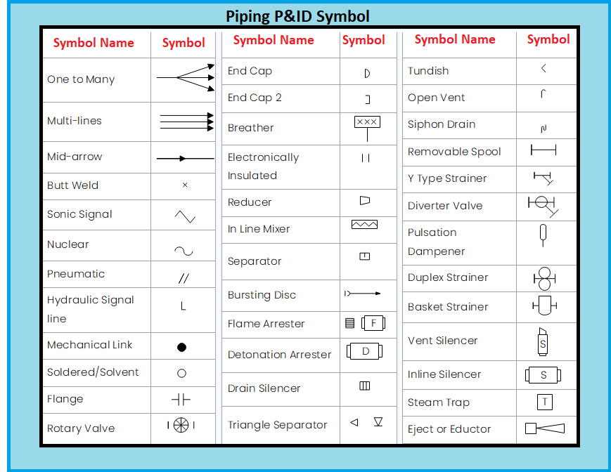
Step 3: Develop a Symbol Library
P&ID symbols are standardized, so you will need to develop a library of symbols that are commonly used in the industry. You can find these symbols in various resources, including standards like ISA 5.1 and ISO 14617. Some software tools, such as AutoCAD and Visio, include built-in symbol libraries.
Step 4: Identify the Process Flow
Once you have identified the equipment and components, you need to determine the direction of the process flow. This is important because it will help you to visualize how the materials are flowing through the system. You should represent the process flow using arrows, which should be drawn in the direction of flow.
Step 5: Create the Drawing
With the equipment, components, symbols, and process flow identified, you can now begin to create the P&ID. Start with a rough sketch and refine it until you have a final drawing. You can use software tools like AutoCAD, SmartDraw, or Visio to create the drawing. Be sure to follow any company or industry-specific guidelines for creating P&IDs.
Step 6: Label the Drawing
Once the drawing is complete, you need to label each component on the drawing. This includes the equipment, piping, and instrumentation. You should also include any important information about each component, such as its size, material, or function.
Step 7: Add Tags and Legends
To identify each component uniquely, you should add tags to each component on the drawing. A tag is a unique identifier that is assigned to each component. You should also create a legend that explains the meaning of each tag and symbol used in the P&ID. This legend should be included on the drawing.
Step 8: Review and Revise
Finally, you should review the P&ID and make any necessary revisions to ensure that it accurately represents the system. Get feedback from others, including operators and engineers, to ensure that it is clear and easy to understand. Once you are satisfied with the P&ID, you can use it for a variety of purposes, such as design, construction, and maintenance.
In addition to the steps outlined above, there are some best practices that you should follow when creating a P&ID:
Use a consistent and logical layout: Arrange the components on the drawing in a logical and consistent manner. This will make it easier to read and understand the drawing.
- Minimize the use of text: Try to use symbols and tags instead of text whenever possible. This will make the drawing easier to read and reduce the chances of errors.
- Use colors sparingly: Use colors sparingly to highlight important components or to distinguish between different systems. Too much color can make the drawing confusing and difficult to read.
To prepare a Piping and Instrumentation Diagram (P&ID), several documents are required to ensure that the drawing accurately reflects the system it represents. The following is a list of some of the documentation that may be necessary:
- Process Flow Diagram (PFD): A PFD is a basic diagram that shows the general flow of the process, including the major equipment and piping. The PFD provides the foundation for the P&ID, which contains more detailed information about the system.
- Equipment Specifications: Equipment specifications provide information about the design and operation of each piece of equipment in the system. This information can include the equipment size, material of construction, capacity, and operating conditions.
- Instrumentation List: An instrumentation list provides a comprehensive list of all the instrumentation and control devices used in the system. This includes sensors, switches, control valves, and other devices.
- Process Data Sheet: A process data sheet provides detailed information about each component in the system, including the size, type, and material of construction. This information is used to select the appropriate equipment and instrumentation for the system.
- Electrical Diagrams: Electrical diagrams show the electrical connections and power requirements for the equipment and instrumentation in the system. These diagrams may include wiring diagrams, control circuit diagrams, and power distribution diagrams.
- Material and Energy Balances: Material and energy balances provide information about the mass and energy flows in the system. This information is used to determine the sizing and selection of equipment and piping.
- Standard Operating Procedures (SOPs): SOPs provide information about the operation and maintenance of the system. This information is used to ensure that the P&ID accurately reflects the current state of the system.
In addition to these documents, it is important to work closely with the stakeholders and subject matter experts involved in the system to ensure that the P&ID accurately reflects the system and its operation. This includes operators, engineers, and other technical experts who have knowledge of the system and its components.