What is Overload in Motors and reason for overload?
Overload is a condition which the motor works in an excess current. which could cause excessive overheating in the motor. In such condition, the motor circuit must be protected.
A motor is said to be overloaded when the motor is under excessive load/current. Overheating, insufficient are the symptoms of overload in motors.
An essential component of any high-power motor control circuit is some device to detect a condition of excessive overload and interrupt power to the motor before thermal damage occurs. A very simple and common overload protective device is known as an overload heater.
Overload protection - Thermal overload heater :
A primary motor protection element of the motor protection relay is the thermal overload element and this is measured by the thermal imaging of the motor. An overload heater consists of resistive elements connected in series with the three lines of a three-phase AC motor. Thermal overload heaters, on the other hand, are specifically designed to protect an electric motor against damage caused by mild overcurrent conditions, such as what might happen if the motor is overloaded mechanically.
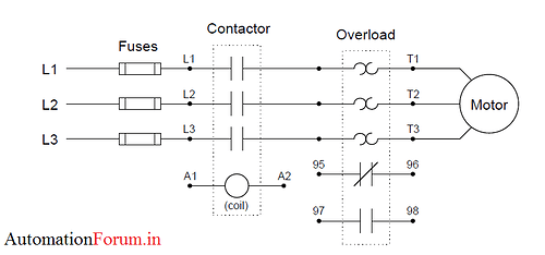
A schematic diagram of a three-phase overload connected to a three-phase contactor and three phase motor is shown here:
The overload set in the circuit responds to the overload function. Both contacts within the overload set will remain in their idle (“normal”) states as long as the heater elements remain cool. However, if one or more of the resistive heaters become too hot, the contacts will activate and change state.
Normally, the normally closed overload contact (terminals 95 and 96) is wired in series with the contactor coil (terminals A1 and A2), so that a detected overload condition forces the conductor to de-energize and interrupt the motor supply.
A typical “trip curve” for a thermal overload unit is shown here, with time plotted against the severity of the overcurrent level:
The mechanisms prevent the overloaded motor from being immediately re-started after a thermal overload “trip” event, giving it time to cool down as well. Hence, the time to reset curve is illustrated in the above graph.

