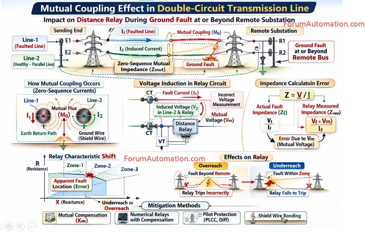
The phenomenon is known as Mutual Coupling due to Zero-Sequence Mutual Impedance.
In double-circuit transmission lines both circuits run in parallel on the same tower.
Because of their physical proximity mutual inductive coupling exists between the circuits especially for zero-sequence currents.
During a single line-to-ground fault zero-sequence current flows through:
• Faulted line conductor,
• Earth return path,
• Ground wire (shield wire),
• Adjacent parallel circuit (healthy circuit).
This creates mutual zero-sequence voltage in the healthy (or) protected line.
How it affects Distance Relay Measurement?
Distance relays calculate impedance using:
Z=V/I
However due to mutual coupling:
The relay measures additional induced voltage.
This voltage is not caused by the actual fault in the protected line.
As a result the relay calculates incorrect apparent impedance.
Effects on Relay Operation
| Condition | Effect on Relay |
|---|---|
| Mutual coupling present | Apparent impedance becomes higher or lower than actual |
| Ground fault beyond remote substation | Relay may underreach or overreach |
| Strong mutual coupling | Increased measurement error |
Possible Relay Errors
1). Overreach Errors
Relay sees fault closer than actual location.
May trip incorrectly.
2). Underreach Errors
Relay sees fault farther than actual location.
May fail to trip when required.
Why this occurs only for Ground Faults?
Mutual coupling mainly affects:
• Zero-sequence current,
• Ground fault protection.
It does not significantly affect:
• Phase-to-phase faults
because zero-sequence current is absent in phase faults.
Example
Consider:
2 parallel 220 kV transmission lines.
Ground fault occurs beyond remote substation.
Due to mutual coupling:
Relay calculates wrong impedance.
Zone-2 protection may overreach into adjacent line.
Mitigation Methods
• Mutual compensation factor (Km) setting in relay
• Use of numerical distance relays with mutual compensation
• Pilot protection schemes (Differential protection, PLCC)
You can also follow us on AutomationForum.co, Facebook and Linkedin to receive daily Instrumentation updates.
You can also follow us on ForumElectrical.com , Facebook and Linkedin to receive daily Electrical updates.