The control power supply of a Variable Frequency Drive (VFD) is essential for the operation of
- Digital inputs,
- Relay logic &
- Communication interfaces.
Most VFDs include a 24 V DC auxiliary output for powering start/stop switches, external relays or PLC input modules.
Before running any control tests ensure that this supply is present & stable.
Verifying Control Power Availability
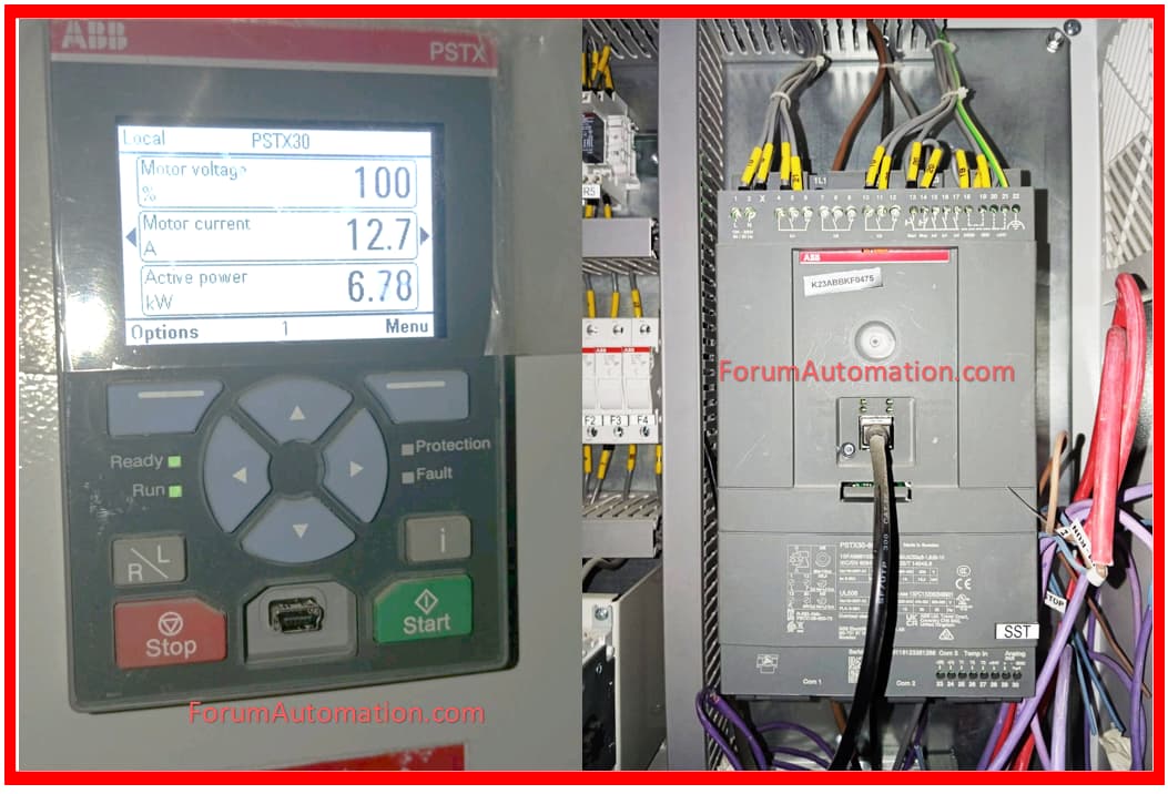
Start by measuring the voltage across the VFD’s control power terminals with a digital multimeter.
The measurement should show a 24 V DC output, indicating that the VFD’s internal control circuitry is properly powered.
Digital input switches such as start, stop, forward & reverse require a constant control voltage to function properly.
Any voltage variations or absence can cause unpredictable VFD functioning or a failure to respond to control signals.
Importance of Digital Input
The VFD’s digital input circuitry directly use the 24 V DC power supply.
When you connect push buttons (or) other input devices, this voltage activates the inputs causing them to perform operations such as start, stop, and mode selection.
Without a dependable control supply, the VFD will fail to recognize input signals causing motor operation to halt or preventing commissioning testing.
To avoid damaging input circuits appropriate polarity and connection must be ensured.
Troubleshooting: Missing Control Voltage
If the multimeter reading displays no voltage or a much lower value, the problem could be driven by a blown control power fuse inside VFD (or) a faulty auxiliary power supply.
Start by evaluating the fuse rated for the 24 V DC circuit & replacing it if blown.
Also, inspect any external DC power connections (or) auxiliary supplies that supply the control circuitry.
Some VFDs need an external DC supply to function properly & a loose or disconnected connection might cause a voltage drop.
Safety Considerations
When accessing panels to inspect fuses (or) wiring, always turn off the VFD or put it in safe mode first.
Utilize insulated tools and adhere to correct lockout/tagout protocols.
Verifying control power without damaging the VFD (or) related devices ensures that the motor control system is safely commissioned and operates reliably.
By thoroughly testing the 24 V DC control supply you ensure that the VFD is ready to respond to digital inputs and control signals laying the groundwork for all subsequent tests such as
- Start/Stop commands,
- Analog speed reference input and
- Communication checks.
You can also follow us on AutomationForum.co, Facebook and Linkedin to receive daily Instrumentation updates.
You can also follow us on ForumElectrical.com , Facebook and Linkedin to receive daily Electrical updates.