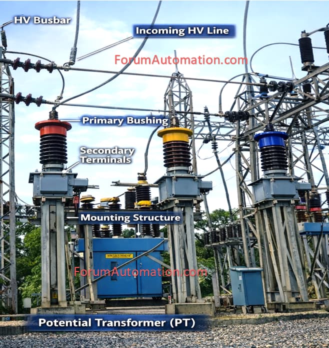
A Potential Transformer (PT) steps down high system voltage to a safe, standardized low voltage for:
1). Metering (energy, voltage, power)
2). Protection relays
3). Control and indication circuits
It must:
• Maintain voltage accuracy
• Withstand system overvoltages
• Supply required VA burden without excessive error
PT Primary Voltage Selection
a) Based on System Voltage
Potential Transformer (PT) primary rating must match system phase voltage.
Voltage. PT Primary (Star)
11 KV 11 / √3 = 6.35kV
33 KV 33 / √3 = 19.05kV
66 kV 66 / √3 = 38.1kV
132 kV 132 / √3 = 76.2kV
Star-connected PTs are most common in most of substations.
PT Secondary Voltage Selection
Standard secondary voltages:
1). 110 V (most common)
2). 110 / √3 = 63.5 V (phase voltage)
3). 100 V (some standards)
Modern relays are designed for 110 V seconds.
PT Burden Calculation (IMP)
Burden is the total VA load connected to the Potential Transformer (PT) secondary.
It includes:
1). Protection relays
2). Metering devices
3). Indicating instruments
4). Cable losses
Device: Burden (VA)
Numerical protection relay: 10VA
Energy meter: 5 VA
Voltmeter: 2 VA
Selector switch + wiring: 3 VA
Total Actual Burden = 10 + 5 + 2 + 3 = 20 VA
Apply Engineering Margin
PT should never be operated at full rated burden.
Recommended margin:
20–30%
Required VA = 20 x 1.25 = 25VA
Selection of PT VA Rating
PTs are manufactured in standard VA ratings:
25 VA
50 VA
100 VA
200 VA
Always select the next higher standard rating.
Selected PT Rating = 50 VA
Accuracy Class Selection
Accuracy class defines maximum permissible voltage error.
Metering PT
Used for billing & measurement:
- Class 0.2
- Class 0.5
Lower number = higher accuracy.
Protection PT
Used for relays:
- Class 3P
- Class 6P
Protection PT focuses primarily on voltage fidelity during faults not billing accuracy.
Voltage Factor (Overvoltage Capability)
PT must withstand temporary overvoltages during:
- Earth faults
- Switching
- Ferroresonance
System Earthing. Voltage Factor
Solidly earthed. 1.2 continuous
Isolated / unearthed. 1.9 for 8 hours
Always check utility / grid code requirement.
Insulation Level
PT insulation must match system BIL.
Example for 11 kV PT:
Rated insulation: 12/28/75 kV
- 12 kV → highest system voltage
- 28 kV → power frequency withstand
- 75 kV → lightning impulse
PT Connection Types
Star–Star → Metering + protection
Open Delta (V-V) → Residual voltage (earth fault detection)
Broken Delta → Zero-sequence voltage (3V₀)
Typical PT Sizing
Example
System: 11 kV, solidly earthed
Secondary: 110 V
Total burden: 20 VA
Margin: 25%
Calculation:
20 x 1.25 = 25 VA
Final Selection:
- PT Ratio: 11 kV / 110 V
- VA Rating: 50 VA
- Accuracy: 0.5 (metering) + 3P (protection)
- Voltage Factor: 1.2 continuous.
You can also follow us on AutomationForum.co, Facebook and Linkedin to receive daily Instrumentation updates.
You can also follow us on ForumElectrical.com , Facebook and Linkedin to receive daily Electrical updates.