What is Mutual Coupling?
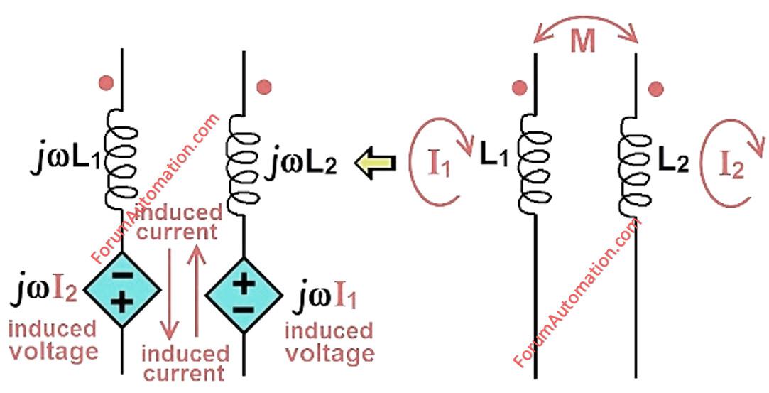
Mutual coupling happens when two or more transmission lines are near together and the magnetic field of one line produces a voltage (or) current in the adjacent line. This phenomenon is typically caused by mutual inductance across lines.
Especially visible in double-circuit transmission cables.
The induced current is a zero-sequence current that flows during ground faults.
Impact on Line Protection
Overcurrent Relays
In the case of a ground fault on one line mutual coupling can cause zero-sequence currents in the neighboring healthy line.
Problem: The relay on the healthy line may detect this induced current & misoperate & tripping even though there is no failure on the line.
Solution: Use negative-sequence (or) directional relays to distinguish between true faults and induced currents.
Distance Relays
Distance relays use impedance to identify defects.
Mutual coupling can affect the perceived impedance, particularly for ground faults.
Problem: The relay may detect a lower (or) higher impedance than the actual fault distance resulting in overreach or underreach.
Solution: Use mutual coupling compensation in relay setups.
To avoid errors when protecting pilots, employ communication-assisted systems.
Differential Protection
Less affected since differential protection differentiates currents entering & exiting a protected zone.
Secondary effects, however, may occur if induced currents are strong.
Ground Faults & Zero Sequence Currents
Mutual coupling is particularly evident for single line-to-ground faults:
The faulty line: zero-sequence current flows normally.
Adjacent healthy line induces zero-sequence current in proportion to mutual impedance.
If not corrected, this might cause ground overcurrent relays to malfunction.
Mitigation Techniques
Mutual Coupling Compensation
-
Adjust relay settings according to mutual impedance estimates.
-
Directed Ground Overcurrent Relays
-
Make sure that only the faulty line trips.
Pilot Protection Schemes
-
Use communication channels across line ends to accurately identify the faulty line.
-
Utilization of phase-selective protection
-
Phase fault detection is less sensitive to the mutual coupling.
You can also follow us on AutomationForum.co, Facebook and Linkedin to receive daily Instrumentation updates.
You can also follow us on ForumElectrical.com , Facebook and Linkedin to receive daily Electrical updates.