How is power distributed from 11kV to 415V in a Typical Industrial Substation?
A power distribution system SLD for an 11kV to 415V substation illustrates the entire flow of electrical power: from the 11kV incoming supply through HT protective devices to the 3500 kVA OLTC transformer & finally into the LT distribution network.
The illustration below demonstrates a typical industrial substation configuration intended for safe, dependable and efficient power transmission.
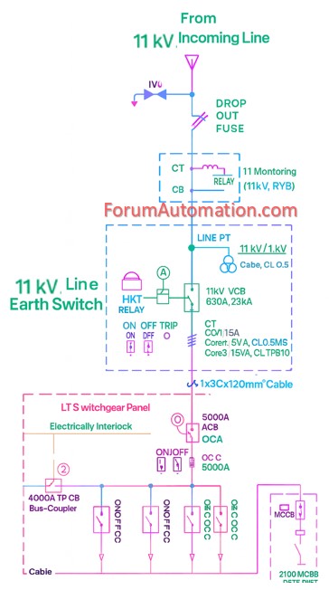
This schematic has all essential components including
- VCB protection,
- CT/PT metering,
- IDMT relays,
- LT ACB incomer,
- Bus coupler interlocking
- PFI compensation system
for power factor management.
Important Features of SLD
11kV HT panel with VCB & numerical protection relays
3500 kVA ONAN oil-filled transformer with OLTC
5000A LT ACB The main incomer uses CT-based metering while the bus coupler has mechanical/electrical interlocking for safety.
A 2100 kVAR PFI (Power Factor Improvement) plant is used for reactive power control.
This SLD was designed to assure effective protection coordination, system reliability & high efficiency in medium-to-large industrial power systems.
You can also follow us on [color=#ff7700]AutomationForum.co[/color], [url= https://www.facebook.com/instrumentation.control][color=#1E00A3]Facebook[/color][/url] and [url= https://www.linkedin.com/showcase/81532759/feed/posts/][color=#1E00A3]Linkedin[/color][/url] to receive daily Instrumentation updates.
You can also follow us on [color=#ff7700] ForumElectrical.com [/color], [color=#1E00A3] Facebook [/color] and [color=#1E00A3] Linkedin[/color] to receive daily Electrical updates.