How Electrical Grounding works?
Electrical grounding (also called earthing) is a safety system that provides a low-resistance path for fault current to flow safely into the earth, preventing electric shock, equipment damage and fire hazards.
How Electrical Grounding Works?
1. Normal Condition (No Fault)
In a healthy electrical system:
- Current flows through the phase (live) conductor.
- Returns through the neutral conductor.
- Ground wire does not carry current during normal operation.
Example:
In a motor or panel, the metallic body is connected to earth, but no current flows through it unless a fault occurs.
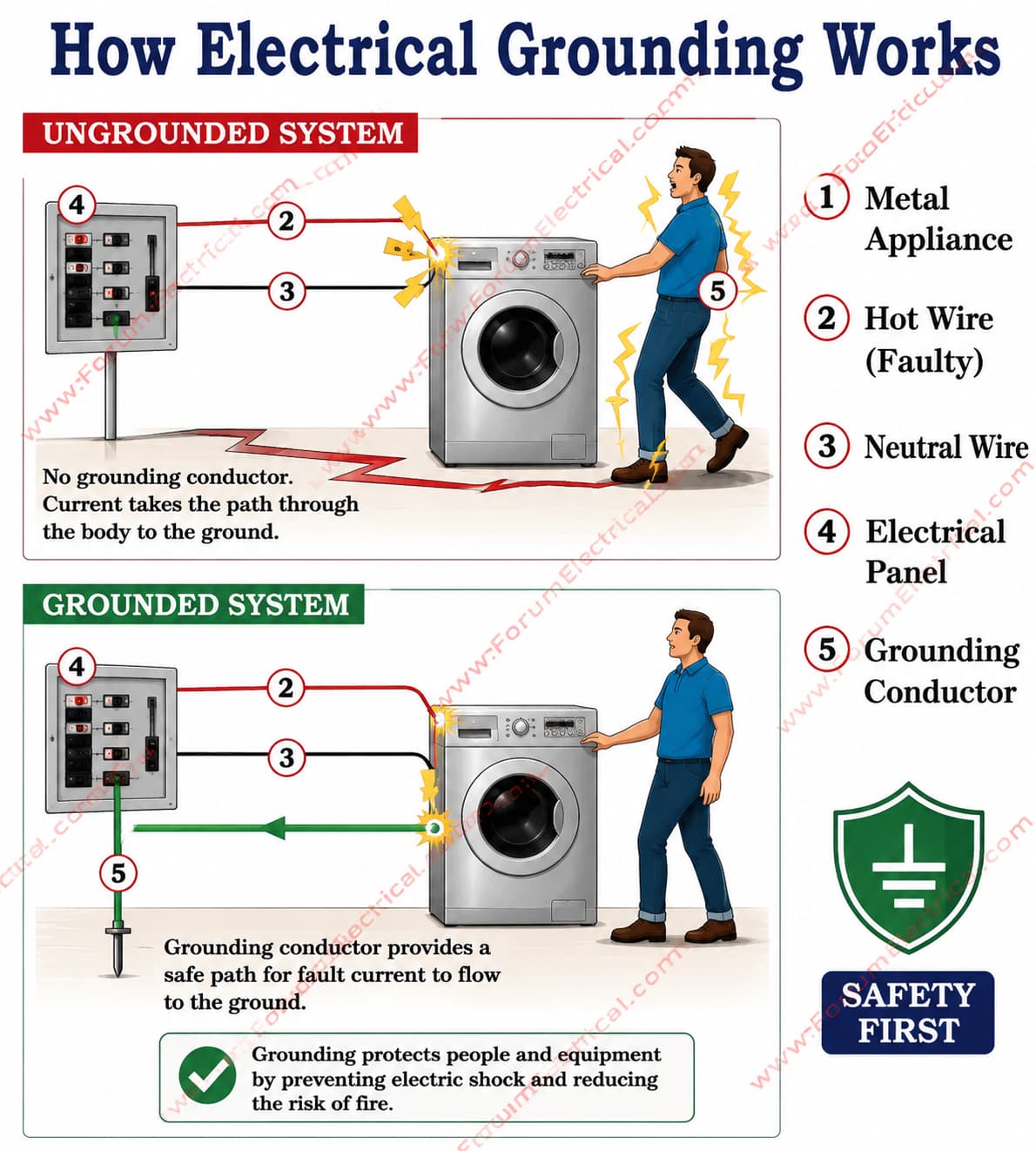
2. Fault Condition (Leakage Current)
Suppose a live wire touches the metal body of a motor or panel.
Without grounding:
The metal body becomes energized and a person touching it can receive an electric shock.
With grounding:
Fault current flows through the earth conductor (lowest resistance path) into the ground.
This large fault current quickly trips protective devices like:
- MCB
- MCCB
- ELCB
- RCCB
- Protective relays in substations
This isolates the faulted equipment.
Basic Working Principle
Grounding works based on this principle:
Electricity always follows the path of least resistance.
The grounding conductor offers a low-impedance path, so dangerous fault current avoids flowing through a person.
Types of Grounding
1. Equipment Grounding (Body Earthing)
Used for motors, transformers, panels, DG sets.
Connects metallic body to earth.
Purpose:
Shock protection
Equipment safety
Example:
Motor body earthing.
2. System Grounding (Neutral Earthing)
Neutral point of transformer/generator connected to earth.
Purpose:
Stabilizes system voltage
Helps fault detection
Limits overvoltage
In substations like 225kV/33kV, transformer neutral grounding is very important.
Common methods:
- Solid grounding
- Resistance grounding
- Reactance grounding
- Petersen coil grounding
Grounding in a Substation
In a substation, a ground grid (earth mat) is buried underground.
It connects:
- Transformer tanks
- Circuit breakers
- CTs/PTs
- Structures
- Lightning arresters
- Control panels
During a fault or lightning strike, current safely dissipates into the soil.
Formula Related to Grounding
The grounding resistance should be low:
R=ρ (L/A)
Where
R = Resistance
ρ (rho) = Soil resistivity
L = Length of conductor
A = Cross-sectional area
Typical grounding resistance values:
- Domestic system: < 5 Ω
- Industrial plant: < 1 Ω
- Substation: < 0.5 Ω (often much lower)
Why Grounding is Important?
- Protects people from electric shock
- Protects transformers and motors
- Prevents fire hazards
- Dissipates lightning current
- Helps relays detect faults quickly
- Stabilizes system voltage
In substations and transformer yards, grounding is one of the most essential safety systems because fault current can be extremely high.