How does Power Line Carrier Communication (PLCC) Work in Transmission Lines?
PLCC is a communication system used in power transmission networks where the transmission line itself is used as the communication medium. It is widely used in 132 kV, 220 kV, 400 kV, and higher voltage substations for teleprotection, voice communication, SCADA, and data transfer.
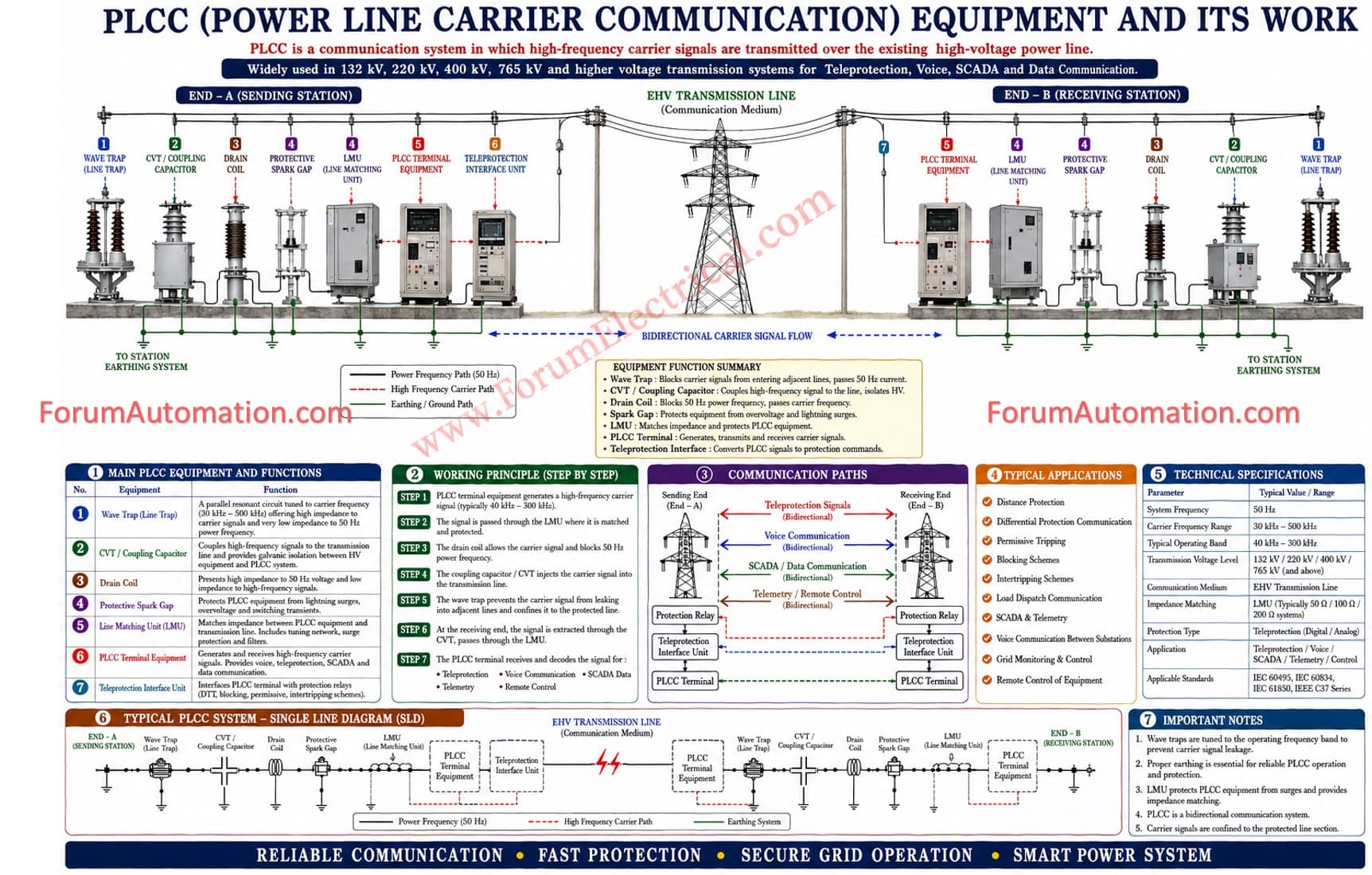
Main PLCC Equipment
1. Wave Trap
Function:
Blocks high-frequency communication signals from entering adjacent transmission lines.
Allows power frequency (50 Hz) current to pass normally.
Installed in series with the transmission line.
2. Coupling Capacitor or CVT
Function:
Couples high-frequency carrier signals to the transmission line.
Isolates communication equipment from high voltage.
3. Line Matching Unit (LMU)
Function:
Matches the impedance between PLCC equipment and transmission line.
Protects communication equipment from surges.
4. PLCC Panel
Function:
Generates, transmits, and receives carrier signals.
Provides voice, teleprotection, and data communication.
5. Teleprotection Equipment
Function:
Sends fault trip signals between substations.
Enables high-speed protection operation during line faults.
Working Principle
-
A carrier signal (typically 30 kHz–500 kHz) is generated by the PLCC panel.
-
The signal passes through the LMU and coupling capacitor/CVT.
-
The signal travels over the high-voltage transmission line.
-
At the receiving end, the coupling capacitor and LMU extract the carrier signal.
-
The PLCC receiver decodes the signal for:
Protection commands Voice communication SCADA data Remote control signals
Applications of PLCC
Distance Protection Tripping Inter-tripping Schemes Load Dispatch Communication SCADA & Telemetry Voice Communication Between Substations Grid Monitoring & Control