How does an Interlocking Control Circuit for Two Motor Contactors work?
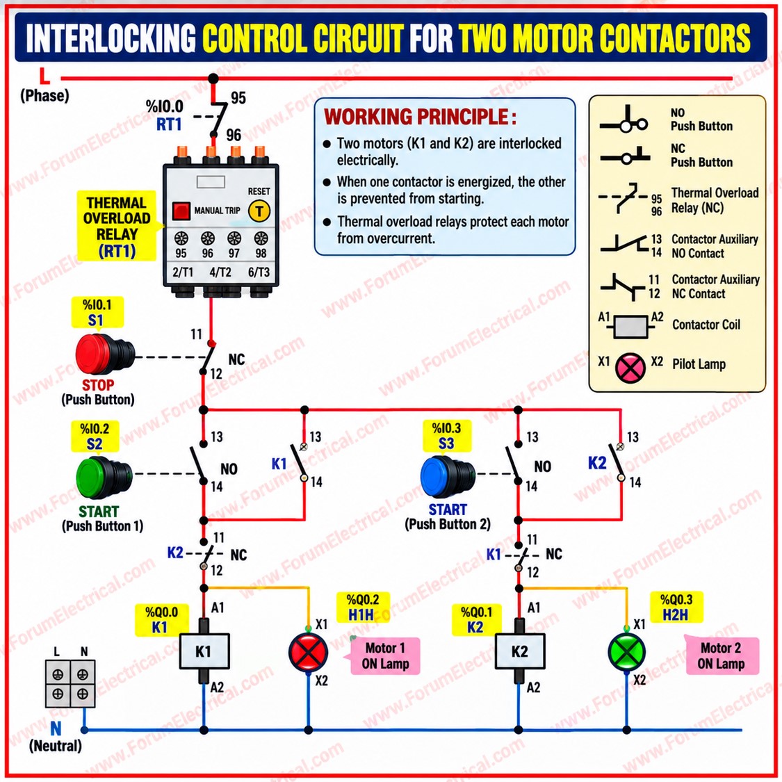
An interlocking control circuit prevents two motor contactors from energizing at the same time, protecting motors and equipment from short circuits or reverse operation.
It combines electrical interlocking using normally closed (NC) auxiliary contacts with mechanical interlocking between the contactors for added safety.
Main Components
K1 & K2: Motor contactors
START 1 / START 2: Push buttons for each motor
STOP: Common stop push button
NC Auxiliary Contacts: Electrical interlocking
Thermal Overload Relay: Motor protection
Mechanical Interlock: Prevents both contactors from closing together
Working Principle
-
Press START 1 to energize K1 and run Motor 1.
-
K1’s NC auxiliary contact opens the K2 control circuit, preventing Motor 2 from starting.
-
Press START 2 only after K1 is de-energized; K2 then runs Motor 2.
-
The STOP button or overload relay de-energizes the active contactor, allowing the other motor to be started.
Applications
-
Forward/Reverse motor control,
-
Two-pump duty/standby systems,
-
Conveyor interlocking and
-
Industrial motor control panels.