A PLC-based traffic signal control system automates traffic lights using a programmable logic controller (PLC).
1). Power Supply Section
110V AC Supply:
The system starts with a standard 110V AC input.
Circuit Breaker:
Protects the system from short circuits and overloads.
AC/DC Power Supply:
Converts 110V AC into 24V DC, necessary to power the PLC and I/O devices.
MCB/Breaker:
Provides additional protection for the PLC and connected devices.
Earth Connection:
Ensures safety and proper grounding of the system.
2). PLC Section (Siemens S7-1200)
The PLC S7-1200 acts as the brain of the traffic signal system.
Inputs (I0.0, I0.1, I0.2 …): Connected to selector switches or sensors to receive ON/OFF signals.
Outputs (Q0.0, Q0.1, Q0.2 …): Connected to traffic lights to control Red, Yellow, and Green lamps.
The PLC processes input signals and controls outputs based on the programmed logic.
3). Terminal Blocks
Terminal blocks organize and connect wiring from:
Power supply
PLC inputs
PLC outputs
Advantages:
Neat and safe wiring
Easy maintenance
Clear labeling of signal paths (e.g., 0VDC, +24VDC, I0.0, Q0.0)
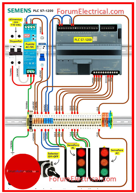
4). Input Devices
Selector Switch (ON/OFF):
Connected to PLC input I0.0.
ON → PLC starts the traffic sequence program.
OFF → PLC stops the cycle.
5). Output Devices (Traffic Lights)
Traffic Light #1 (Semáforo #1):
Red, Yellow, Green lamps connected to PLC outputs (Q0.0, Q0.1, Q0.2).
Traffic Light #2 (Semáforo #2):
Another set of Red, Yellow, Green lamps connected to outputs (Q0.3, Q0.4, Q0.5).
The PLC ensures only the correct lamp is ON at a time based on the programmed traffic sequence.
6). Working Logic
Power ON → Selector switch activates the system.
PLC runs traffic sequence:
Semáforo #1 → Red ON, Semáforo #2 → Green ON
Transition → Both Yellow ON
Semáforo #1 → Green ON, Semáforo #2 → Red ON
Cycle repeats continuously to maintain safe traffic flow.
7). Programming Role
Programming is done in TIA Portal (Siemens software).
Logic ensures proper timing for each signal:
Red = 30s
Green = 25s
Yellow = 5s
Timings can be adjusted according to traffic requirements.
A PLC-based traffic control system uses a 24V DC-powered Siemens S7-1200 PLC. Inputs from a selector switch trigger the PLC program which controls two traffic lights in a safe and continuous sequence using Red, Yellow and Green signals.
You can also follow us on AutomationForum.co, Facebook and Linkedin to receive daily Instrumentation updates.
You can also follow us on ForumElectrical.com , Facebook and Linkedin to receive daily Electrical updates.