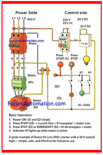
The following illustration shows a functional motor control circuit that includes both power and control parts.
It is a traditional Direct-On-Line (DOL) starting configuration that is often used in industrial environments. Appropriate for students, field technicians, & automation engineers.
Power Section (Left side - 440V 3 Phase AC)
-
Q1 - Motor Circuit Breaker: Protects motor and wires from overcurrent and short circuits.
-
K1 - Electrical Contactor: Switches three-phase electricity to motor. Controlled by a circuit.
-
Cables & Terminals: Heavy-duty industrial cables & terminal blocks provide safe, heat-resistant wiring.
-
M1 - 3-Phase Motor: The main load is usually an induction motor for fans, pumps, or conveyors.
Power Flow Path: L1, L2, L3 → Q1 → K1 → Motor Terminals (U1, V1, W1).
Control Section (Right Side: 220V AC Converted to 24V DC)
-
Q2 - Control Circuit Breaker: Protects low-voltage (LV) control side from faults.
-
Power Supply (AC/DC Converter): The power supply (AC/DC Converter) converts 220V AC to 24V DC for safe powering the control circuit.
-
F1 - Control Fuse: Provides additional protection against the overcurrent in control wire.
-
S1 - Emergency Stop (NC): A normally closed pushbutton that immediately stops the circuit when pressed.
-
S2 – STOP Button (NC): When pressed, the S2 - STOP Button (NC) interrupts the circuit and de-energizes the contactor.
-
S3 - START Button (NO): A normally open pushbutton that accomplishes the circuit and activates the contactor coil.
-
K1 Coil – Contactor Actuation (A1/A2): When energized, the K1 Coil - Contactor Actuation (A1/A2) closes the primary contactor, providing power to the motor.
-
H1 – Indicator Lamp: The H1 - Indicator Lamp provides visual input when the motor is running.
Basic Operating Sequence
-
To power up the circuit, close Q1 (power side) & Q2 (control side) simultaneously.
-
To start the motor, press the START button (S3). The control voltage energizes the K1 coil, the main contactor closes, and the motor starts.
-
To stop the motor, press the STOP button (S2) (or) Emergency Stop (S1). The control circuit opens, K1 de-energizes, and the motor stops.
-
The indicator lamp H1 flashes when the motor is running, confirming its active condition.
Why This Setup Is Ideal Safe?
-
24V DC control minimizes shock danger.
-
Simple wiring allows for easy troubleshooting.
-
Compliant with DOL starting logic used in automation panels around the world.
Applications
-
Motorized conveyor belts,
-
HVAC blowers,
-
Water pump, and
-
Small industrial machinery.
