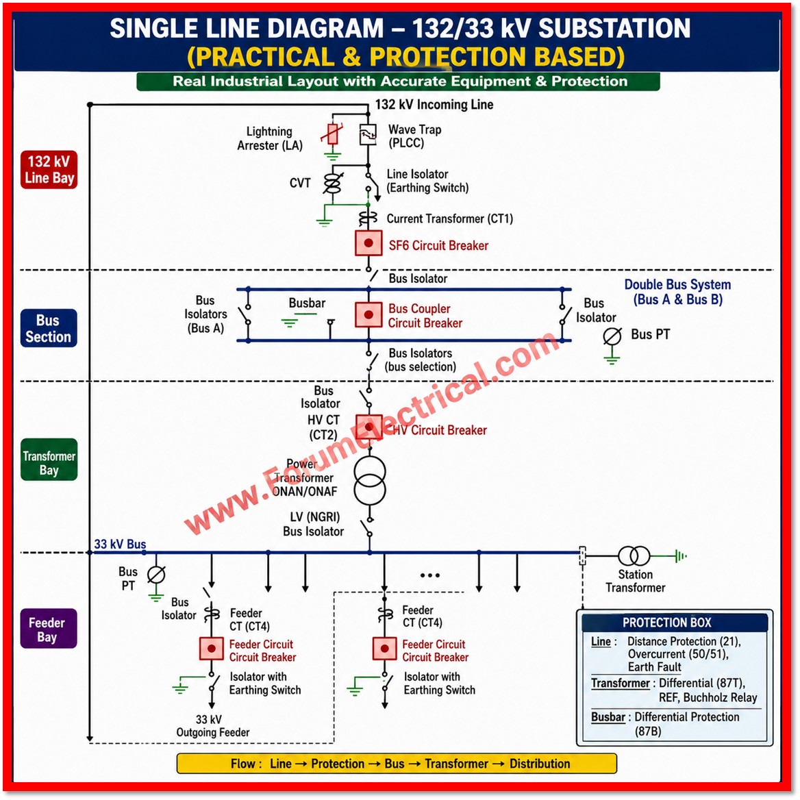
A 132/33 kV substation SLD provides a clear representation of power flow, major electrical equipment, switching arrangements, and protection systems. It helps engineers understand how high-voltage power is received, transformed, protected, and distributed to outgoing 33 kV feeders.
132 kV Incoming Line
The incoming 132 kV line typically includes Lightning Arresters, CVT, Wave Trap/PLCC equipment, Isolators, CTs, and SF₆ Circuit Breakers for protection, measurement, communication, and safe isolation.
Double Busbar System
The 132 kV switchyard may use a double bus arrangement with a bus coupler and bus PT. This configuration provides operational flexibility, facilitates maintenance, and improves supply continuity.
132/33 kV Transformer Bay
The transformer bay includes HV CT, Circuit Breaker, 132/33 kV Power Transformer, and LV-side isolation equipment. The transformer reduces the incoming voltage from 132 kV to 33 kV for distribution.
33 kV Distribution System
The 33 kV bus section includes Bus PTs, Feeder CTs, Circuit Breakers, and outgoing feeders, allowing electrical power to be distributed safely to downstream loads and networks.
Protection System
Key protection functions include Distance Protection (21), Overcurrent (50/51), Earth Fault, Transformer Differential (87T), Restricted Earth Fault (REF), Buchholz Protection, and Busbar Differential Protection (87B).
Why is this SLD Important?
Understanding a 132/33 kV substation SLD is essential for substation design, protection coordination, testing and commissioning, operation, maintenance, and fault troubleshooting. A skilled electrical engineer must understand both the power-flow path and the protection philosophy used to detect and selectively isolate faults.