Process to Determine Locked Rotor Current (LRC)
Lock the Rotor
Physically prevent the rotor from rotating.
Apply Reduced Voltage
Apply low voltage (to avoid damage) at rated frequency.
Measure Current
Use an ammeter or clamp meter to measure stator current.
Extrapolate to Full Voltage
LRC is proportional to voltage → calculate current at rated voltage.
Typical Value
LRC ≈ 5 to 7 times full load current (FLC)
Formula
ILRC ∝ V
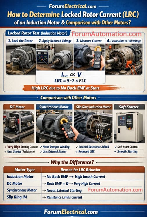
Comparison with Other Motors
Induction Motor
High LRC due to no back EMF at start
Rotor current induced → behaves like short circuit
DC Motor
LRC is very high initially.
Controlled using starter (resistance) to limit current.
Synchronous Motor
No inherent starting torque.
Uses damper winding / external starter.
LRC not directly measured like induction motor.
Slip Ring Induction Motor
External resistance added → reduces LRC.
Better control of starting current.
Why the Difference?
| Motor Type | Reason for LRC Behaviour |
|---|---|
| Induction Motor | No back EMF → high inrush current |
| DC Motor | Back EMF = 0 at start → very high current |
| Synchronous Motor | Needs external starting → different behaviour |
| Slip Ring IM | External resistance limits current |
You can also follow us on AutomationForum.co, Facebook and Linkedin to receive daily Instrumentation updates.
You can also follow us on ForumElectrical.com , Facebook and Linkedin to receive daily Electrical updates.