
To direct oil into various hydraulic system circuits, directional control valves are employed. The first factors to take into account are the maximum flow capacity and the pressure drop through the valve. Directional
Control valves may connect to electronic, hydraulic, pneumatic, and manual controls. The majority of these variables are chosen during the original system design.
The actuator in a hydraulic system receives supply oil via the directional control valve.
The valve body is heat treated sometimes, after being drilled and sharpened.
The ports for the intake and outflow are threaded and drilled. High quality steel was used to manufacture the valve spool. Some valve spools have been heated, treated, sized, and polished. Other valve spools are polished, chrome-plated, and ground to size. The valve body and valve spool are next assembled in accordance with the design requirements. The only component that moves after assembly is the valve spool.
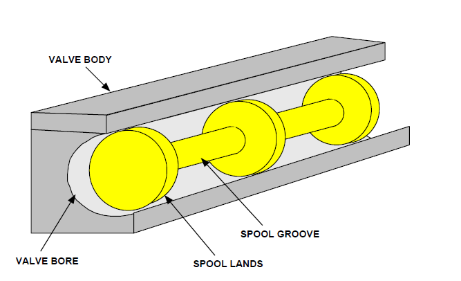
Pump Spool
The valve spool is made up of grooves and lands (Figure). Oil cannot flow through the valve body because of the spool lands. Oil may go through the valve body and around the spool thanks to the spool grooves.
The “normal” position of the spool refers to its state when it is not triggered.
An “open center” valve feeds supply oil through it and back to the tank when it is in the typical position. A “close center” valve’s spool blocks the delivery of oil while it is in the typical position.
Open Center Directional Control Valve in HOLD Position
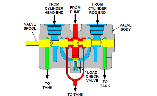
A typical open center directional control valve in the HOLD position is shown cutaway in Figure.
The pump oil flows into the valve body, around the valve spool, and back into the tank while the valve is in the HOLD position. The load check valve receives oil from the pump as well. Oil has clogged up the passageway behind the load check. The load check valve is kept closed by the clogged oil and the load check valve spring. Moreover, the valve spool prevents oil from reaching the rod end and cylinder head end.
Open Center Directional Control Valve in RAISE Position
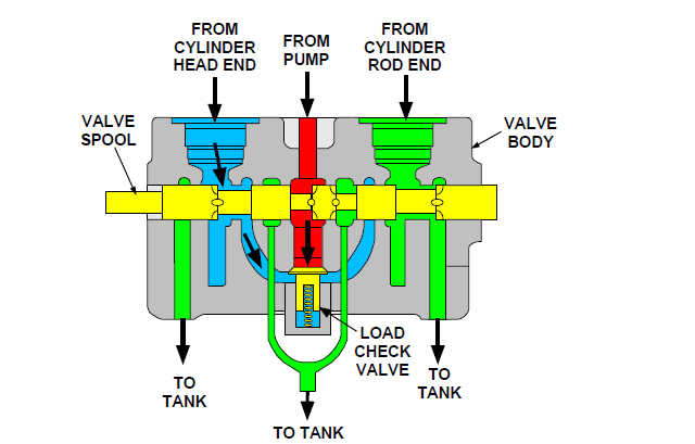
The valve spool is seen in Figure as it moves to the RAISE position.
The pump oil flow to the tank is stopped when the valve spool is turned to the RAISE position. Yet, the load check valve is open to the flow of pump oil. The cylinder rod end and the tank passage are also connected to the oil behind the load check valve via the valve spool. The load check valve keeps the oil in the head end of the cylinder from flowing into the pump oil passage. The pump’s restricted oil flow raises the oil pressure.

Figure shows that the pressure behind the load check valve is overcome by an increase in pump oil pressure (unseats the load check valve).
Pump oil passes to the cylinder’s head end after passing via the load check valve and the valve spool.
The oil in the cylinder’s rod end runs through the valve spool and into the tank.
Basic Envelope

A basic envelope or many basic envelopes make up the basic valve ISO symbol seen in Figure. The amount of locations the valve may be adjusted is represented by the number of envelopes utilized.
Valve Port
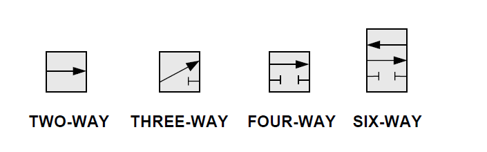
Figure shows valve ports for working lines. The term “two-way valve” is often used to describe a valve having two ports. Contrast this with the two-position valve seen in Figure . Valves may have whatever many ports and positions are required. All the same, the majority of valve locations and valve ports fall between the numbers one and three.
Flow Path
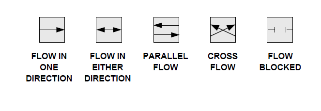
The flow pathways and directions between ports are essentially represented by the lines and arrows within the envelopes in Figure.
Three Position Valve
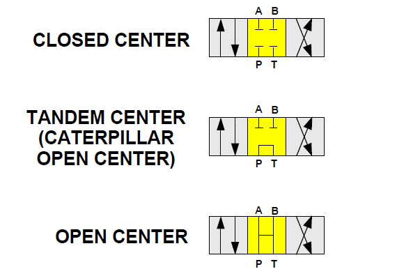
Three ISO symbols for the three-position valve are shown in the figure. The neutral or hold position is the middle position of the three-position valve. When the valve is not functioning, it is position HOLD is used for.
The middle position has several uses depending on the spool’s design.
A closed center valve is represented by the ISO symbol at the top. The closed center spool shuts off all oil flow while it is in the HOLD position.
A tandem center valve is represented by the ISO symbol in the center.
The tandem center valve links the pump to the tank while blocking oil flow at A and B while it is in the HOLD position.
A central valve that is open is represented by the ISO symbol at the bottom.
The open center valve links all ports to the tank while it is in the HOLD position.
Three Position, Six Way, Open Center, Manual Controlled Valve

A three position, six way, open center, manually operated valve is shown in the HOLD position in Figure. Pump oil travels to the tank by passing via the valve spool. The control valve spool is blocking the oil in the cylinder.
Three Position, Six Way, Close Center, Pilot Controlled Valve

Figure depicts a pilot-controlled valve with three positions, six ways, and a close center. All oil flow is stopped at the control valve spool while the valve is in the HOLD position.
Directional Control Valve Actuator
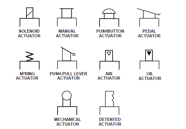
Figure displays the ISO symbols for several actuators for directional control valves.