How can PLC Ladder Logic automate a Three-Phase AC Motor?
The following example shows a basic PLC program for controlling a three-phase AC motor with full automatic operation through a user-friendly screen interface. The system has been divided into three major sections:
1). Power Circuit
The power circuit shows the whole path of the motor’s electrical supply. Power is routed from the incoming source to a Magnetic Circuit Breaker (MCB) for protection, subsequently via a contactor and then to a thermal relay. The thermal relay protects the motor from overloads, reducing overheating & potential damage from too much current.
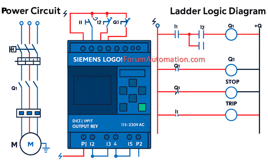
2). Siemens Logo! PLC
The Siemens LOGO! is a small, easy-to-use PLC designed for small-scale automation operations. Also known as a logic module, it integrates the functionality of a standard PLC, operator interface & communication module into a single unit.
Core Components:
- CPU: Runs the control program.
- Integrated I/O: The system includes digital inputs (I1, I2, I3, I4) & outputs (Q1, Q2, Q3, Q4) for interfacing with sensors & actuators.
- Power Supply: Terminals P1 and P2 can support several voltages (12V DC, 24V AC/DC or 115/230V AC).
- Display & Keypad: Enables on-device programming, monitoring & diagnostics.
- Ethernet Interface: Accessible in LOGO! There are eight models that cover networking, programming & web server functions.
3). Ladder Logic Diagram
The control logic is executed utilizing ladder logic, a PLC programming language that simulates electrical relay logic with vertical “rails” and horizontal “rungs.” The program consists of 4 rungs.
Rung 1: The motor coil is energized by three contacts (Start, Stop & Trip).
Rung 2: Q1, a normally open (NO) contact, controls the RUN indication bulb.
Rung 3: The STOP indicator bulb is controlled by the normally closed (NC) contact Q1.
Rung 4: When an overload occurs, Input I1 triggers the TRIP lamp.
This configuration maintains consistent motor functioning and provides clear visual feedback for running, stopping & fault conditions.
You can also follow us on AutomationForum.co, Facebook and Linkedin to receive daily Instrumentation updates.
You can also follow us on ForumElectrical.com , Facebook and Linkedin to receive daily Electrical updates.