Ground Resistance Testing
Ground resistance testing is important for electrical projects to guarantee safety, system integrity & standard compliance.
2 popular & reliable testing methods are:
- Fall-of-Potential Method
- Four-Pole / Slope Method
1). Fall-of-Potential Method
Ideal for small to medium grounding systems with enough space to place test probes.
Electrode setup (E, P, C) & spacing are normal (starting distances between 20m and 40m depending on system).
V/I calculation is the correct fundamental principle.
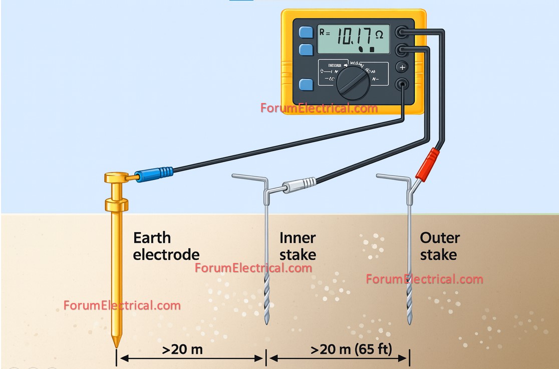
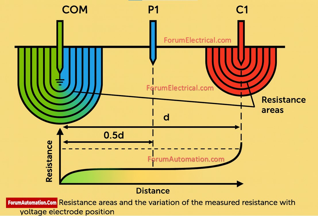
To accurately measure resistance it’s recommended to move the potential probe and plot a curve to locate the “flat region” (commonly as a potential gradient curve).
2). Four-Pole / Slope Method
Suitable for big systems where normal spacing for Fall-of-Potential is not feasible.
This method uses four electrodes in a straight line with identical spacing, accounting for soil resistivity and geometrical variables making it ideal for large grids.
When used for soil resistivity, it is commonly referred to as the Wenner method whereas in other forms it is known as Schlumberger.
Best Practices
- Maintain adequate electrode distances.
- Test from multiple directions for improved accuracy.
- Dry soil leads to higher resistance.
- Soil resistivity tests are necessary throughout the design process particularly for substations or plants.
Standards Reference
These methods align with IEEE Std 81 & IEC 60050 which provides rules for measuring earth resistivity, ground impedance & surface potential.
You can also follow us on AutomationForum.co, Facebook and Linkedin to receive daily Instrumentation updates.
You can also follow us on ForumElectrical.com , Facebook and Linkedin to receive daily Electrical updates.