Electrical interlocking is a critical safety and control function in HT/LT switchgear systems, designed to prevent incorrect switching operations and unwanted paralleling of power sources.
In a typical incomer–bus coupler–incomer arrangement, the tie/bus-coupler breaker should close only when the required electrical and protection conditions are satisfied.
Typical Interlocking Conditions
- Incomer Breaker Status,
- Bus Coupler / Tie Breaker Status,
- Source Availability,
- Bus Voltage Status,
- Protection Relay Permissives,
- Isolator / Earthing Switch Position,
- Synchronizing Conditions, where applicable
- Local/Remote & Control Logic Permissives
Key Advantages
- Prevents Incorrect Switching,
- Reduces Risk of Unwanted Paralleling,
- Improves Power Supply Reliability,
- Enables Controlled Load Transfer,
- Reduces Process Downtime,
- Supports Safer Maintenance Activities,
- Improves Operational Flexibility and
- Protects Electrical Equipment.
QA/QC & Commissioning
During FAT, SAT, pre-commissioning and commissioning, interlocking logic must be verified against the approved:
- Single Line Diagram (SLD),
- Protection & Control Philosophy,
- Cause & Effect / Logic Diagram,
- Switchgear Schematics,
- Interlocking Matrix and
- Approved Plant SOP.
Important: Actual operating sequences depend on the switchgear configuration, protection philosophy, synchronization requirements, control logic and approved plant operating procedure.
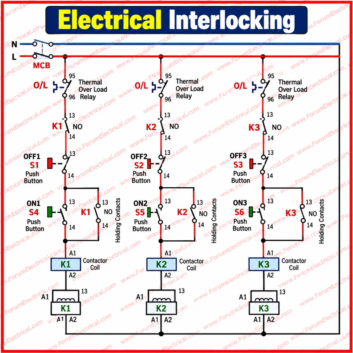
Reliable Power Distribution is not only about equipment: it is about correct protection, effective interlocking and disciplined operation.
Interlocking = Safety + Reliability + Controlled Operation