Electrical Cable Sizing
Proper electrical cable sizing is essential for safe and reliable power distribution. An undersized conductor can lead to excessive temperature rise, voltage drop, insulation deterioration, and potential fire hazards.
4 critical factors determine the correct cable cross-sectional area.
1. Current-Carrying Capacity
For a three-phase load, the design current is calculated as:
I = P / (√3 × V × PF × η)
Example:
Power = 30 kW
Supply Voltage = 415 V
Power Factor = 0.85
Efficiency = 0.90
Design Current = 30,000 / (1.732 × 415 × 0.85 × 0.90)
Calculated current ≈ 54.5 A
The selected cable must carry the design current after applying the relevant correction and derating factors.
2. Voltage Drop Calculation
For a three-phase AC circuit:
ΔV ≈ √3 × I × L × (R cos φ + X sin φ)
Where R is cable resistance, X is cable reactance, L is the one-way cable length, and φ is the load power-factor angle. All quantities must use consistent units.
3. Short-Circuit Thermal Withstand
The minimum conductor cross-sectional area can be estimated using the adiabatic equation:
S = I × √t / k
Where S is the conductor cross-sectional area in mm², I is the prospective fault current in amperes, t is the fault-clearing duration in seconds, and k is the material- and insulation-dependent constant.
Example:
Fault Current = 5,000 A
Fault Duration = 0.2 seconds
Assumed k = 115 for a suitable copper/PVC application
Calculated minimum area:
S = 5000 × √0.2 / 115
S ≈ 19.4 mm²
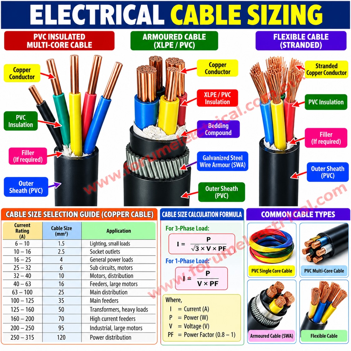
The next suitable standard cable size must be verified against the applicable installation conditions, conductor temperature limits, and relevant standards.
4. Cable Derating Factors
Cable selection must account for ambient temperature, grouping of loaded cables, installation method, soil thermal resistivity for buried cables, conductor material, and insulation temperature rating.
An important electrical design relationship is:
Ib ≤ In ≤ Iz
Where Ib is the design current, In is the protective device rated current or applicable setting, and Iz is the cable current-carrying capacity after applying relevant correction factors. Additional protection requirements must also be satisfied.
Final cable selection should verify current-carrying capacity, permissible voltage drop, short-circuit withstand, automatic fault disconnection, harmonics where applicable, and compliance with relevant IS/IEC standards and project specifications.