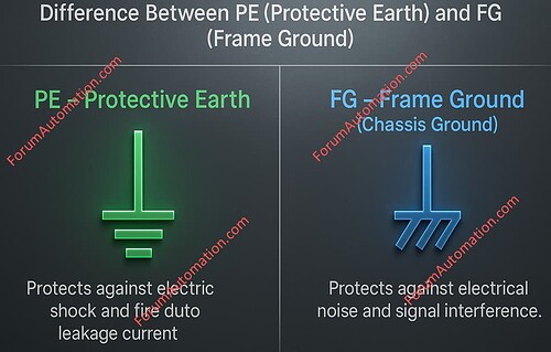
Protective Earth (PE)
Symbol Significance: Grounding for Protection (Protective Earth).
Purpose: The PE connection protects people and equipment from electric shock & fire threats due by leakage current (or) insulation failure.
It assures that exposed conductive components are safely connected to the earth potential.
In case of a failure, current goes directly to the ground allowing protection devices (such as circuit breakers) to activate immediately.
Key Function: Provides safe grounding for the electrical protection.
Frame Ground (FG)
Symbol Significance: Grounding of metallic frames (or) structures (Frame Ground/Chassis Ground).
Purpose: The FG connection is primarily intended to protect electronic equipment against electrical noise & signal interference rather than electrical shock.
It ensures that the metal frame of equipment (such as control panels, PLC enclosures or drives) has the same potential hence eliminating undesired electromagnetic interference.
It is commonly found in the control systems, communication equipment and sensitive electronics.
Key Function: Signal grounding reduces noise and improves system stability.
Difference between PE Symbol and FG Symbol
PE Symbol vs FG Symbol
| Parameter | PE (Protective Earth) | FG (Frame Ground / Chassis Ground) |
|---|---|---|
| Full Form | Protective Earth | Frame Ground (or) Chassis Ground |
| Purpose | Provides safety grounding to protect people and equipment from electric shock and fire caused by leakage current. | Provides signal or frame grounding to minimize electrical noise, EMI and interference in sensitive circuits. |
| Function Type | Safety Ground | Noise / Signal Ground |
| Primary Use | Ensures fault current flows directly to earth, enabling circuit breakers or protective devices to operate. | Stabilizes potential differences in electronic chassis and reduces high-frequency interference. |
| Voltage Range | Commonly used in power systems (Low Voltage, Medium Voltage, High Voltage). | Used mainly in control systems, communication, PLCs and electronic equipment. |
| Connection Point | Connected to the earth electrode or grounding grid of the electrical system. | Connected to the metal frame or chassis of the device (may or may not be connected to earth). |
| Color Identification | Green or Green/Yellow striped wire. | Blue or Black wire (varies by standard). |
| Protection Provided | Against electric shock, insulation failure, and fire hazards. | Against electrical noise, signal distortion, and EMI. |
| Typical Applications | Switchgear, transformers, motors, distribution panels, and building grounding systems. | Control panels, PLC systems, instrumentation and communication devices. |
| Symbol Appearance | A vertical line above three horizontal bars of decreasing length. | A vertical line above three angled (diagonal) lines. |
You can also follow us on AutomationForum.co, Facebook and Linkedin to receive daily Instrumentation updates.
You can also follow us on ForumElectrical.com , Facebook and Linkedin to receive daily Electrical updates.
