Control valves are used in process control systems to regulate the flow of fluid, gas or steam. These symbols are used in process flow diagrams, P&IDs (piping and instrumentation diagrams), and other engineering drawings to indicate the type and location of control valves in a process system. Here are some of the commonly used control valve symbols:
The most commonly used control valve symbols are the globe valve, gate valve, ball valve, butterfly valve, diaphragm valve, needle valve, three-way valve, check valve, and solenoid valve.
The symbols are used in process flow diagrams, P&IDs (piping and instrumentation diagrams), and other engineering drawings to indicate the type and location of control valves in a process system. The symbols provide a standardized way to represent control valves in engineering drawings, making it easier for engineers and technicians to understand and communicate about process control systems.
The symbols are used in process flow diagrams, P&IDs (piping and instrumentation diagrams), and other engineering drawings to indicate the type and location of control valves in a process system. The symbols provide a standardized way to represent control valves in engineering drawings, making it easier for engineers and technicians to understand and communicate about process control systems.
In addition to the symbols, annotations are often used to provide additional information about the valve, such as its size, materials, and control function. For example, a globe valve might be labeled with the words “1-inch globe valve, stainless steel body, pneumatic actuator.” This annotation provides important information about the valve’s size, materials, and control function, which helps engineers and technicians to understand how the valve fits into the larger process control system.
Valve Symbols for P&IDs
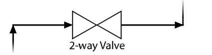
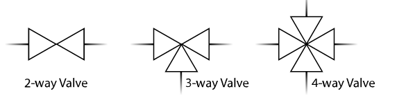
Two triangles pointing in the same direction and meeting at their innermost points serve as the universal representation of a two-way valve. Lines joining to either side of the valve symbol depict the pipe lines. Several line kinds are used to depict various pipes, tubes, and hoses. In these illustrations, basic solid pipes or tubing are represented by single solid lines. All pipes typically employ just right angles and travel either vertically or horizontally. An arrowhead at the end of the line where it joins the next component and at each 90-degree turn indicates the direction of flow.
Type of Valve
A pattern is added to the middle where the points contact to show the kind of valve. The P&ID symbols for the most popular kinds of valves are shown here.
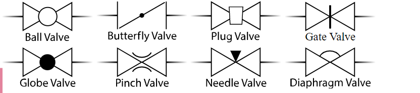
All of the valves shown above are two-way inline valves used for throttling or on/off flow control. Similar symbol layout is used for multi-port valves, such as 3-way and 4-way valves, with a triangle standing in for each port or “way.”
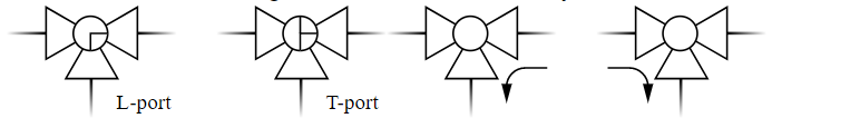
Ball valves with three and four ways may also include information that specifies whether the ball drilling is a “T” port ball or a “L” port ball. The flow channel in the inactive or de-energized condition may also be included in the diagram as an additional feature. This is shown below using smaller arrows adjacent to the symbol.
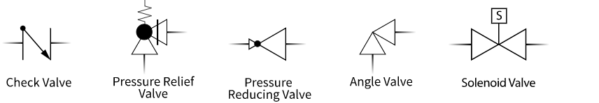
There are other additional valve varieties as well. These are a few examples.
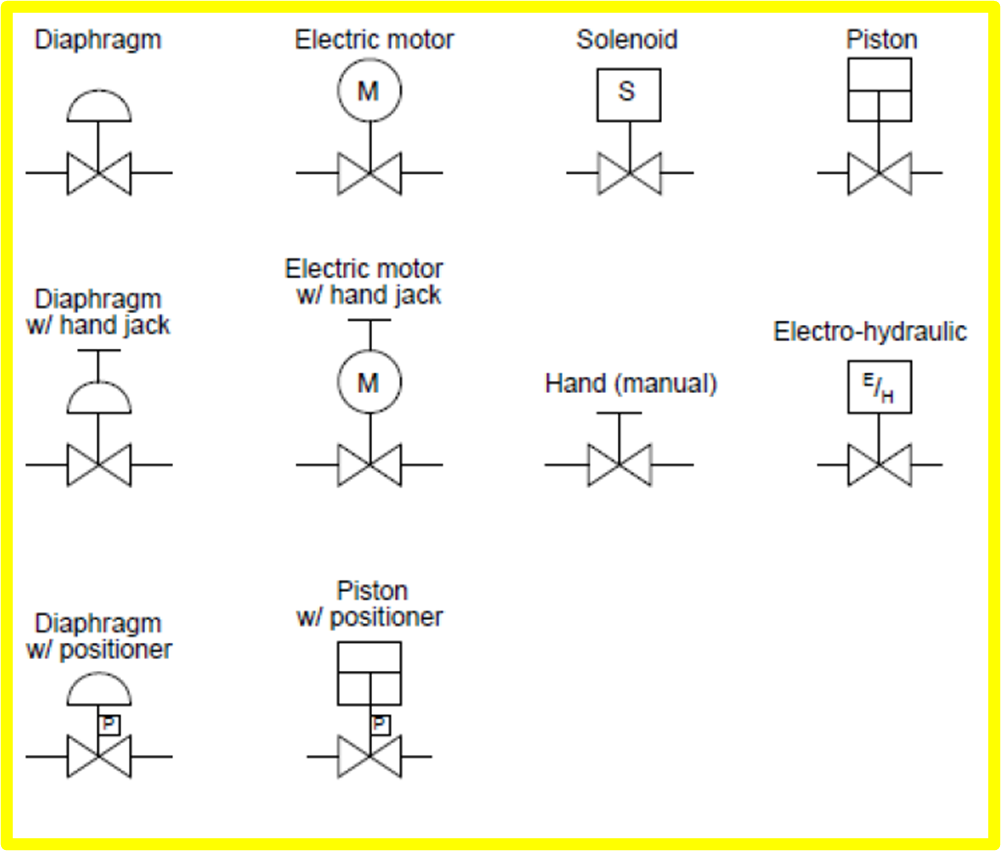
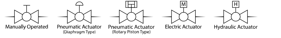
Type of Actuator
A line rising from the center of the valve and ending with a tiny symbol, often a letter, designates the manner of actuation. Below are some illustrations of various actuation techniques for ball valves.
Fail-Safe Position
An arrow is shown on the wire connecting the actuator and valve when the actuator has a fail-safe position. Two characters, “FO” or “FC,” are another way to indicate the fail position.

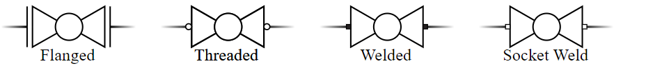
End Connections
The lines representing the pipes entering the valve directly, like in all of the aforementioned examples, might serve as a general representation of end connections. There are many additional ways to explicitly specify connections. In the illustration below, flanged connections are represented by pipes with perpendicular lines at their ends that run parallel to the sides of the valve sign and a short space between them. This demonstrates that it is possible to remove the valve without having to cut the pipe. Little hollow rings at the connecting location indicate semi-permanent threaded connections. Little squares are used to indicate permanent welded connections. If a socket weld is used for the connection, the square will be empty or hollow.