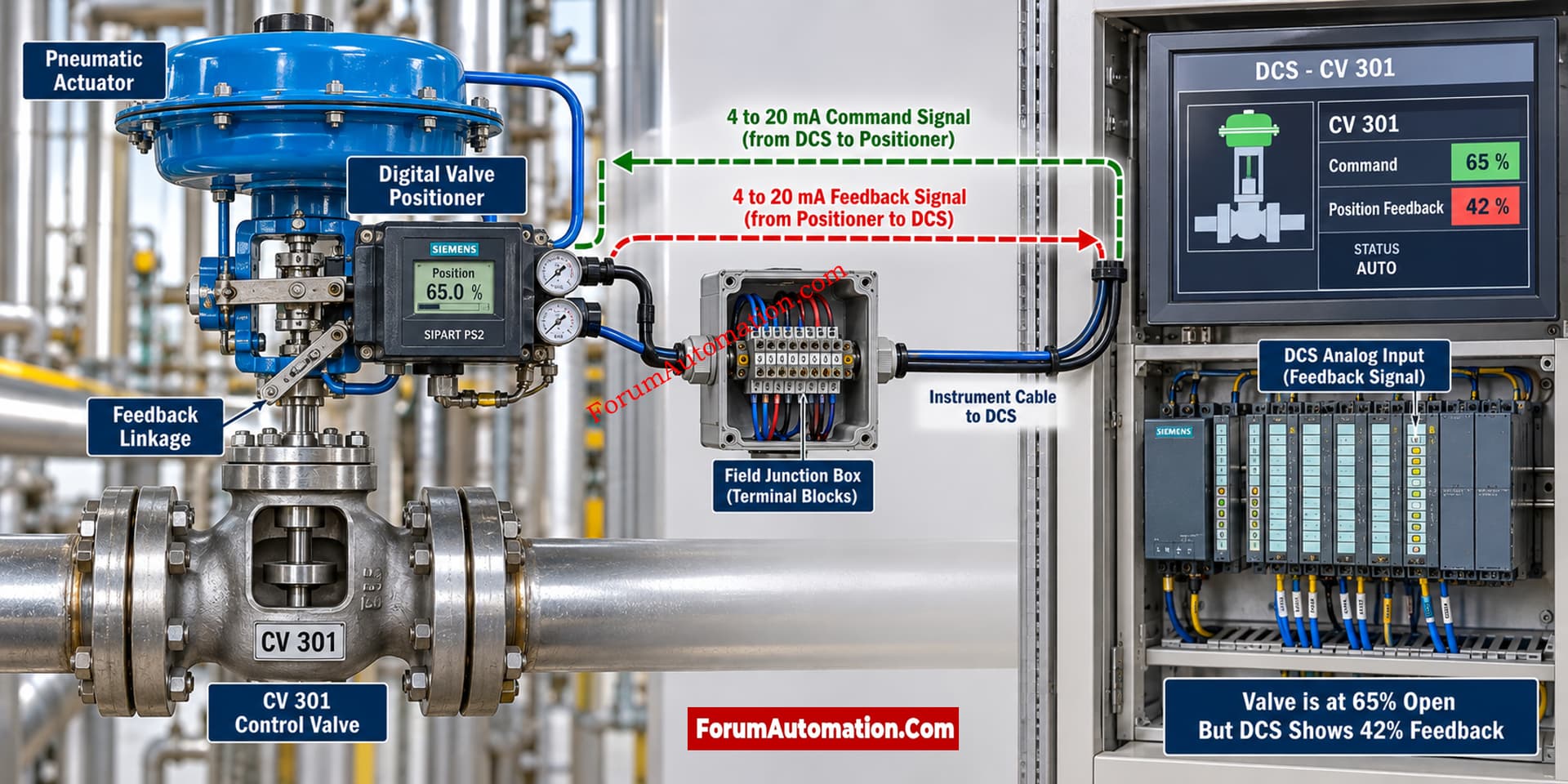
The first step should be to determine whether the problem is mechanical valve position, positioner calibration, feedback linkage, feedback sensor, signal wiring, or DCS scaling.
Since the valve appears to respond to commands but the feedback does not correspond to the actual position, the feedback system should be checked independently from the valve command signal.
Most Likely Causes
Typical causes are incorrect positioner calibration, incorrectly adjusted feedback linkage, loose mechanical coupling, incorrect zero/span setting, damaged position feedback sensor, incorrect 4 to 20 mA scaling, incorrect DCS input configuration, or mechanical travel not matching the configured valve stroke.
Where a separate valve position transmitter is used this should also be tested for calibration and mechanical connectivity.
What Should Be Checked First?
The initial check should be to verify the actual position of the valve stem or shaft with the position indicated by the positioner and the DCS.
For example, if the valve is physically at approximately 65 percent travel but the DCS indicates 42 percent, the engineer should determine where the discrepancy begins.
Measure the feedback signal at the source and compare it with the signal received at the DCS input.
A typical position feedback signal may be configured as 4 mA for 0 percent and 20 mA for 100 percent, but the actual project configuration must always be verified.
Recommended Troubleshooting Sequence
- Place the valve in a safe operating condition according to the approved procedure.
- Verify the actual mechanical valve position.
- Check the positioner local position indication.
- Compare the positioner indication with the physical valve travel.
- Check the feedback link and the mechanical coupling.
- Look for loose or poorly mounted linkage components.
- Measure the feedback current at the positioner or feedback transmitter.
- Measure the same signal at the marshalling or DCS input.
- Verify DCS scaling and engineering range.
- Check the positioner zero and span configuration.
- If required, perform an approved valve stroke test.
- Compare the final position at various points (0%, 25%, 50%, 75% and 100%).
An Important Diagnostic Clue
If the feedback is wrong at every position but changes proportionally with valve movement, incorrect calibration or scaling should be investigated.
If the feedback suddenly jumps, remains fixed, or becomes erratic at certain positions, a mechanical linkage problem or feedback sensor problem may be more likely.
If the feedback is correct at the positioner but incorrect at the DCS, the problem is more likely to be in the signal transmission, termination, analog input configuration, or DCS scaling.
Practical Recommendation
Do not immediately replace the valve positioner or feedback transmitter.
First, define three independent values:
True mechanical valve position
Positioner, indicated position
DCS defined position
Looking at these three figures in comparison helps to pinpoint exactly where the gap lies, and avoids the wasteful replacement of healthy equipment.