Capacitive Charging Current in Transmission Lines: Causes, Effects, and Control
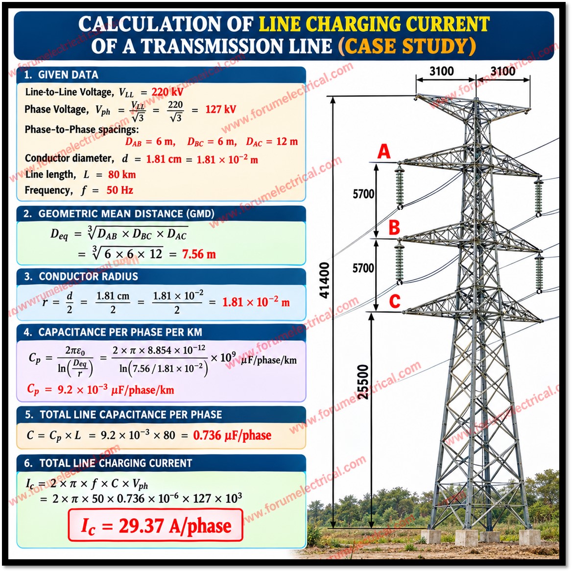
Capacitive charging current is the leading current drawn by the distributed capacitance of an AC transmission line, even under no-load conditions. It depends on the system frequency, operating voltage, phase capacitance, and line length.
For a single-phase equivalent circuit:
Ic = 2πfCV
Where:
Ic = Capacitive charging current (A)
f = System frequency (Hz)
C = Capacitance (F)
V = Applied RMS voltage (V)
For a balanced three-phase system, charging current is calculated using the per-phase capacitance and phase-to-neutral voltage.
Key Technical Effects:
Ferranti Effect: Receiving-end voltage may exceed sending-end voltage under light-load or no-load conditions due to distributed line capacitance.
Capacitive Reactive Power: Transmission lines generate leading reactive power, potentially causing voltage rise during low-load operation.
Conductor Losses: Charging current contributes to conductor I²R losses, even when useful load current is absent.
Voltage Regulation: Excessive capacitive charging can complicate voltage control and increase insulation stress.
System Stability: Effective reactive power management is essential for reliable operation of long-distance, high-voltage transmission networks.
Methods of Charging Current Compensation:
Shunt reactors absorb excess capacitive reactive power and limit voltage rise.
Reactive power compensation supports voltage regulation and reactive power balance.
Controlled switching reduces switching transients during line energization and de-energization.
Load-flow and electromagnetic transient studies help determine reactor ratings and appropriate compensation strategies.
Capacitive charging current is particularly important in long-distance 400 kV and 765 kV AC transmission networks. Understanding its effects is essential for transmission-line design, insulation coordination, reactive power management, and reliable grid operation.