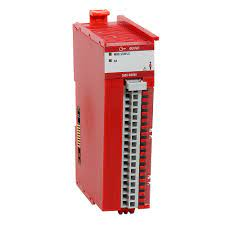
Allen Bradley 5380 Safety output 5069-OBV8S Circuit Fault
I recently encountered a red output light on my Allen Bradley 5380 safety digital output (5069-OBV8S) indicating a circuit fault. How can I program an alarm to notify the HMI when this occurs again?

To program an alarm to notify the HMI when a circuit fault occurs on your Allen Bradley 5380 Safety output (5069-OBV8S), you’ll need to follow these steps:
Identify the Fault Condition:
- Determine how the 5069-OBV8S module reports the circuit fault. Typically, this information is available through a status tag in the controller.
Create a Fault Monitoring Routine in the PLC:
- Use the status tag associated with the 5069-OBV8S to monitor the fault condition in your PLC program. This might involve checking a specific bit that indicates a fault.
Set Up an Alarm Bit:
- When the fault condition is detected, set an alarm bit in your PLC program. This bit will be used to trigger the HMI alarm.
Configure the HMI Alarm:
- Set up an alarm in your HMI software (e.g., FactoryTalk View) that monitors the alarm bit you set in the PLC.
Here’s a more detailed step-by-step process:
Step 1: Identify the Fault Condition
Check the Module Status Tags:
- The 5069-OBV8S module has status tags that indicate various conditions, including faults. Refer to the module’s documentation to identify the specific tag and bit that indicates a circuit fault.
Step 2: Create a Fault Monitoring Routine
Open Your PLC Program:
- In Studio 5000 Logix Designer, open the program for your 5380 controller.
Add a New Routine:
- Create a new routine or use an existing one where you will monitor the fault status.
Monitor the Fault Bit:
- Use a GSV (Get System Value) instruction or directly access the status tag to check for the fault condition. For example:
ladder configuration
GSV
    Class Name: Module
    Instance Name: "YourModuleName"
    Attribute Name: "FaultCode"
    Dest: FaultStatus
- If
FaultStatus indicates a fault (non-zero), set an alarm bit:
ladder ladder configuration
XIC FaultStatus OTE AlarmBit
Step 3: Set Up an Alarm Bit
Define an Alarm Bit:
- Create a new Boolean tag in your PLC program, e.g.,
AlarmBit.
Set the Alarm Bit:
- In your fault monitoring logic, set this bit when a fault is detected.
ladder configuration
XIC FaultStatus OTE AlarmBit
Step 4: Configure the HMI Alarm
Open Your HMI Software:
- Open FactoryTalk View Studio or your preferred HMI configuration software.
Create a New Alarm:
- Go to the Alarm Setup section and create a new alarm.
Configure the Alarm to Monitor the Alarm Bit:
- Set the trigger for the alarm to be the
AlarmBit tag in your PLC.
Set Alarm Properties:
- Define the message and any other properties for the alarm, such as priority and acknowledgment requirements.
Example in FactoryTalk View:
Add a New Alarm:
- Go to Alarms and Events > Alarm Setup > Digital Alarms.
Define the Alarm Trigger:
- In the Digital Alarm setup, set the trigger tag to
AlarmBit.
Set Alarm Message:
- Define the message that will be displayed on the HMI when the alarm is triggered, e.g., “Safety Output Circuit Fault Detected.”
Configure Alarm Properties:
- Set the priority, category, and any acknowledgment settings as needed.
By following these steps, you will have a system that monitors for circuit faults on your 5069-OBV8S module and triggers an alarm on the HMI when a fault is detected. This will help in promptly notifying operators and taking corrective actions.
