ACB (Air Circuit Breaker) Wiring Diagram
An ACB (Air Circuit Breaker) wiring diagram is a detailed electrical drawing that shows the control and power wiring connections of an air circuit breaker.
It illustrates how components such as the
- Closing coil,
- Trip coil,
- Auxiliary contacts,
- Shunt trip,
- Undervoltage release,
- Motor charging mechanism and
- Protection relays
are interconnected to ensure safe operation and reliable protection.
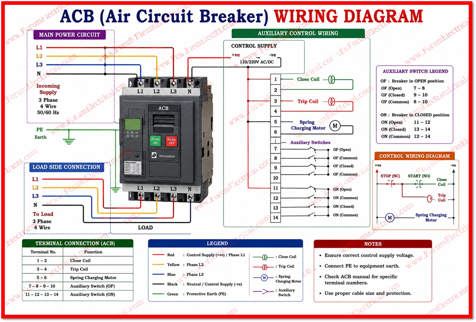
The wiring diagram helps engineers, electricians, and maintenance personnel correctly install, commission, troubleshoot and maintain the air circuit breaker. It also ensures proper coordination between the breaker, protection relays, and control circuits.
A typical ACB wiring diagram includes the
- Main power terminals,
- Control supply,
- ON/OFF push buttons,
- Spring charging motor,
- Closing and trip coils,
- Auxiliary contacts,
- Protection relay connections,
- Indication lamps and
- Remote operation terminals.
Understanding an ACB wiring diagram simplifies fault diagnosis, minimizes installation errors, improves maintenance efficiency and ensures the breaker operates safely during normal operation and fault conditions in low-voltage power distribution systems.